Welcome to my second OSL tutorial. Again, we will not write a single line of code in this tutorial. We will use SlateME as our OSL editor. Let me say it again, YOU DON’T NEED TO KNOW HOW TO CODE TO USE OSL IN 3dsMax.
I don’t want to spoil the ending. But, you should read til the end. 🙂
One of the advantage(or could be disadvantage for some users) of using OSL in 3dsMax is that it brings more granular and lower level of control which provide a greater flexibility. But, it also means that user need to learn and understand a new way of thinking(or workflow). Again it doesn’t mean you need to learn to code. But, you need to understand how and what kinds of data is flowing between lower level maps and how to control them. So, please try pay more attention to the explanation of “why” I’m connect port A to port B instead of memorizing map tree. 🙂
Today’s goal is randomizing textures in the tiles of Simple Tiles OSL shader so we can get infinite random tile texture from a few texture files.
 Open SlateME.
- Make a Simple Tiles map. Maps > OSL > Textures > Simple Tiles.
This is an equivalent of Tiles legacy map. You can make a various tile or brick patterns. - Double click the thumbnail so we can have a bugger thumbnail.
- Change Tiling Mode to Twist Box.
As you can see, OSL can output not only color information but also various data information. For this tutorial, we will mainly utilize Index data which is a integer index number for individual tiles. Let’s see that it means visually.
 Make 2 OSL > Math Float > Random by Index.
- Connect Index port of Simple Tiles to Idx of both Random by Index map.
So, what’s happening here?
Random by Index map generates a random float number between Min and Max and drives the randomization with the Idx and Seed parameters.
Since Idx of Random by Index is provided by the Index value of Simple Tiles, all pixels in the same tile will get the same random value.You can see that well from the thumbnail, each tile has a different shade of gray.
But, you can see both map has exactly same pattern and color. That’s because both map has same Seed number by default. What is the Seed number? This is from the Wikipedia. “A random seed (or seed state, or just seed) is a number (or vector) used to initialize a pseudorandom number generator.”, which brings another important concept, pseudorandom.
In CG, we can not use true random number, if a number is truly random. That means every time when you render or even open file again. You will have a different number and different pattern! Therefore, all random number in CG is pseudorandom driven by Seed number. If Seed number is same you get the same ransom number just like the above image.
- Select the bottom Random by Index map
- Set Seed to “77”, You should get this.

OK. let’s make a bunch more maps and actually do something with these 2 random maps.
- Make the following maps
OSL > Math Vector > Component (Vector)
OSL > UVWCoordinates > UVW Transform
OSL > BitmapLookUp - Choose “C:\Program Files\Autodesk\3ds Max 2021\maps\uvwunwrap\uv_checker.png” for BitmapLookUp
This is a new 4k UV template which is added in 2021. - Connect Out of the top Random by Index > X of Component (Vector)
- Connect Out of the bottom Random by Index > Y of Component (Vector)
- Connect Out of the Component (Vector) > Offset of UVW Transform
Do not connect anything to BitmapLookUp yet.
The 2 Random by Index we made were for the random Offset value of UVW, and it is a vector value. How do I know? If you see in UI, you can ses that it is made out of 3 values. The, it is a vector value.
So, we can not directly plug 2 float values into the Offset port. We need to assemble a vector data and plug into Offset. Component (Vector) map allow to compose or decompose a vector from/to 3 floats. Since we need to use only X and Y value. you don’t have to plug anything into Z. If no map is connected to the property, OSL map will use the value in the UI which was 0.
What we got so far? As you see in the thumbnail of UVW Transform, we randomly offset UV per tile. If you see more red, that means the pixel is offset more along U. If you see more green, that means the pixel is offset more along V. Remember Slate can only show any value range from 0-1 because it is made for color. Fortunately this case out data range is also 0-1. So, we could see what’s going on as image. But, it would be be the case all the time.
- Now Connect UVW of the UVW Transform > UV Coordinates of BitmapLookUp
Tada! you can see your texture randomly offset by Tile ID.
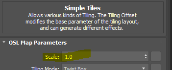
Cool. Now how can I control the scale of texture? Yes, you change the Scale value of UVW Transform.

How can I control the size of tiles? Scale in Simple Tiles.
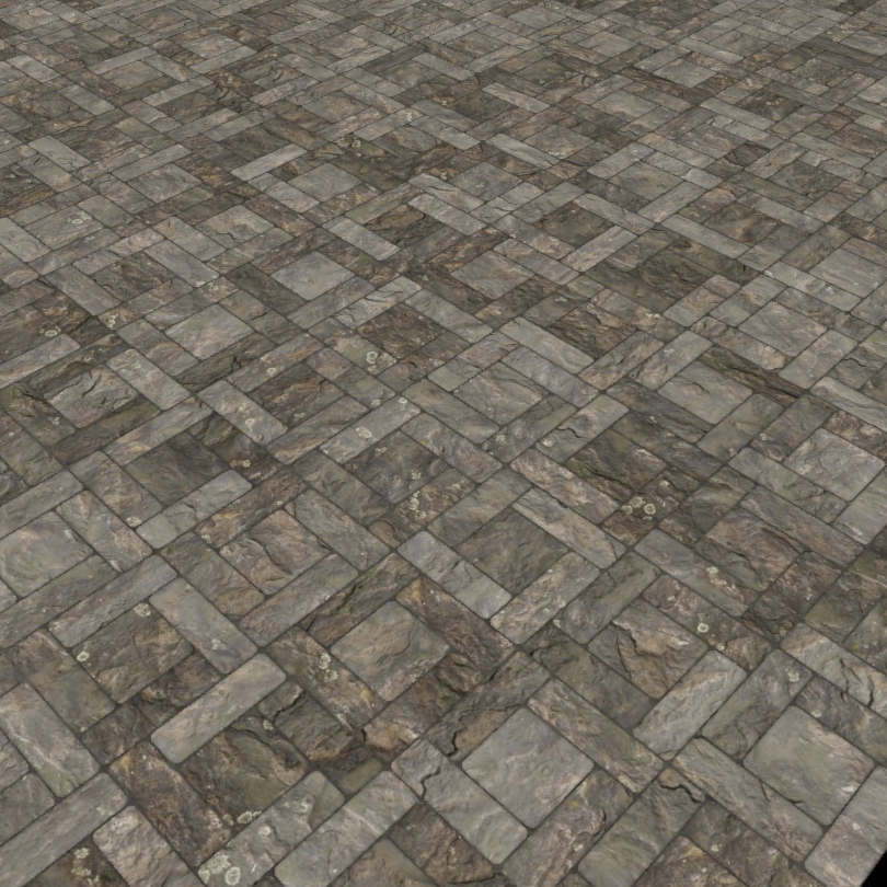
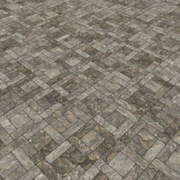
Let’s see what it looks like with a real texture. Remember this technique only works with seamless tileable texture. This is with the TexturesCom_RockSmooth0172_1_seamless_S.jpg from here. https://www.textures.com/. I use scale to 5.0 for UV.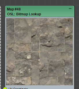
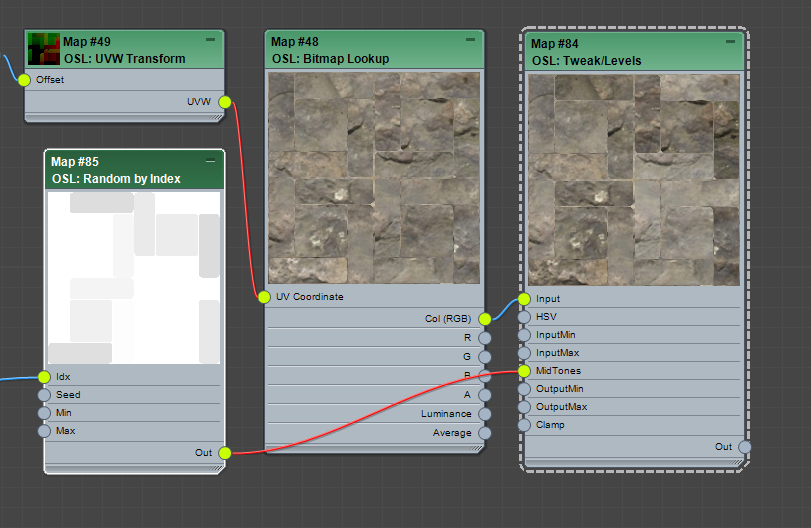
How about some mid tone variation? We can use Tweak/Levels OSL map for this. We will also need another Random by Index map driven by Index.
- Select one of Random by Index map and SHIFT+drag to make a copy.
- Set Min as 0.75, Max as 1.25. Seed as 131.
- Add a OSL > Tweak/Levels map.
- Connect Out of the new Random by Index map to MidTones of Tweak/Levels.
- Connect Out(RGB) of BitmapLookUp map to the Input of Tweak/Levels.
OK, I hope you get the hang of how to wrangle data to drive values at this point. Next, let’s put the gaps in. There are unlimited ways to how to handle gaps. But, I’ll just go easiest way since the main purpose of this post is tutorial. The Bump output of Simple Tiles map already give you a black gaps and white tiles. I’ll use that output to composite with Multiply mode.
- Make OSL > Compositing > Composite map.
- Connect Out of the Tweak/Levels > Bottom layer RGB of Composite
- Connect Bump of the Simple Tiles > Top layer RGB of Composite
- Set Top layer Alpha as 0.7, BlendMode as Multiply.

OK, it is getting there. Let’s add one more randomization, the rotation. By now, you should already know what to do.Yes, you need to have another Random by Index (Float) with range 0.1 – 360 and feed into Rotate of UVW Transform. BUT, since it is a tutorial, let’s make things more complicate to learn. What if we want to rotate only at right angle like 90, 180, 270 degree?
Our goal is get only one of the 0, 90, 180. 270 per tile. How we do that? Right, we can get a random value between 0 – 3 and multiply 90.0. But, Random by Index (Float) generates float number, and we don’t have Random by Index (Integer) map. Well, don’t worry. Here comes Float-to-Int map to the rescue!
- Copy one of Random by Index (Float).
- Set Min as 0.0, Max as 3.99. Seed as 666.
- Make OSL > Math Float > Float-to-Int map
- Set Mode as floor.
- Make OSL > Math Float > Multiply map
- Set B as 90.0
- Connect Out of the new Random by Index map to Input of Float-to-Int.
- Connect Out of the Float-to-Int map to A of Multiply
- Connect Out of the Multiply map to Rotate of UVW Transform.

You may wonder why 3.99 instead of 3.00, and what the heck is “floor”? Floor is a way to convert a float value to integer value by returning the largest whole number (integer) that is less than or equal to the number. if you had 1.24, you would get 1.o. So, it is a floor of the range 1.0-2.0. There is also “ceil” which is kinda opposite. The ceil of 1.24 would be 2.0. By setting range as 0.0-3.99 and mode as floor, we are trying to make sure all 4 numbers are getting even chance. 0.0-1;0 > 0.0. 1.0-1.99 > 1, 2.0-2.99 > 2.0. 3.0-3.99 > 3.0.
Left is without the rotation randomization. Right is with the rotation randomization.
 As you can see, you can randomize any parameters you want. You just need to know when to stop. Should we stop now then? No, not yet. So far, we have used only one map file and looks like getting a good result. But, what if we can use multiple map files and randomly use per file?
Here is a great news. One of the new feature of 3dsMax 2021.2 is 1-of-N(Filename) map. If we don’t have this map, we have to setup a small tree with multiple BitmapLookup , 1-of-N Switcher and Random by Index map. Now we just need 2 maps.
- Add a OSL > Switchers > 1-of-N(Filename) map.
- Choose all 5 maps.
- Add a OSL > Switchers > Random Index by Number/Color map. BTW, such a great map, I wonder who made this? 🙂
- Connect Index of the Simple Tiles map to Input Number of Random Index by Number/Color.
- Connect Out of the Random Index by Number/Color to Filename of BitmapLookUp.

OK… This is the full tree. I guess we end up with not-so-mini-tutorial.
BUT! Yes, there is always. “BUT”.
We went through all these to learn how to work with OSL maps to build own randomization. Now I have to tell you this. Sorry, we didn’t need to go through all these if you wanted to just use it. Why? Because Zap made the awesome Bitmap Random Tiling for 3dsMax 2021.2.
This is what it looks like if you use Bitmap Random Tiling. Youjust need to plug Index into Seed. Make sure to turn off Randomize by UV position.
You can even randomize color, too.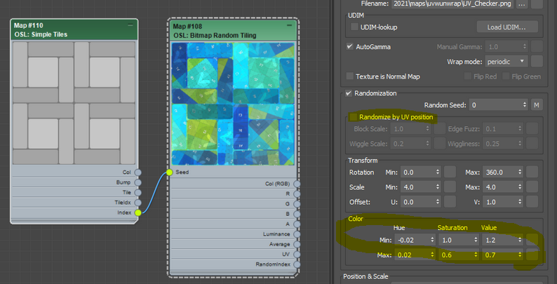
If you want to use multiple map file? Then, re-use the 1-of-N(Filename). Another 2021.2 feature.
I guess it is worth to upgrade??? 🙂
If you are really lazy, here is the max file. It has the full setup and simple 2021.2 setup. I can not include texture file. So, you probably need to download some seamless tileable maps. Here is another good news. Because ,max file actually embed the source OSL code in the scene file, you can even open this file in 2019. You will see the new 2021.2 OSL shader there. Save the OSL map in a material library. Then, you can even use the new map in 2019 or 2020. Another nice thing about 3dsMax OSL implementation!
Click to download .max file of this tutorial (2019 version)Since you follow me all the way down here, you need to check renderStacks. Click here!
A teaser for the future article! What is the difference between the following 4 images?


The answer is… they all rendered in a different renderer. From the left, Corona, VRay, VRayGPU, Arnold. Yes, all different renderer. You can have exactly same map tree across different renderer even CPU/GPU. I can say this is the first time I ever see this is possible in CG history. I’ll have a blog post with more examples in the future.