Menu Close

Author: changsooeun

MCG : Camera Map Multi

This MCG modifier allows you generate multiple camera projected UV with independant resolition per camera. It is essentially  a MCG version of CameraMapGemini.
3dsMax 2018+


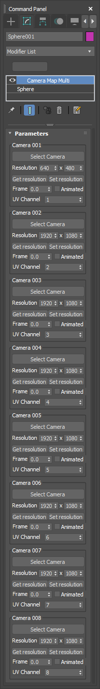
Download MCG : Camera Map Multi


Compare to the built-in Camera Map modifier, Camera Map Mult provide the following additional features.

  • Multiple camera support up to 8 cameras
  • Resolution per camera
  • Animated camera support

How to use is very simple. Select a camera with Select Camera button. Then, set the resolution and the frame to project. If you just want to project from the current camera animation, turn on Animated. Then the Frame value will be lock to the current frame. The Frame value is animatable so you can have more control than just matching to the current frame. The last option to set is which UV channel you want to use. For your convinience, there are also Get resolution and Set resolution button to get/set reslution from Render Setup dialog.

I know it CemeraMapSemini had also a companion map. But, making a map plugin is beyond my capacbility.  But, who knows someday I might. Let’s cross fingers. 🙂

It is free as always.

A special thanks to Kelvin Zelt at Autodesk for helping me to solve the last piece of puzzle.


MaxFluids PRT Export Channel Setup

Download MaxFluidsPRTExportChannelSetup

3dsMax 2018.4 has been released today.
https://area.autodesk.com/blogs/the-3ds-max-blog/meet-3ds-max-2018-4/

One of the feature is the full BiFrost channel support for PRT export.
You can export all BiFrost channels even with custom channel names.

As of now, export channel setup is only exposed to Maxscript.
So, I made a UI for that.

You can turn on/off channels and rename channels.

Installation is simple.
Download the zip file and drag and drop to your viewport.
You can find the script in csTools > MaxFluidsPRTExportChannelSetup.
It is a macroscript so you can make button, menu or shortcut.
It will also show up in Global Search(X)

As always, it is free!

3dsMax DataChannel Modifier Sample Pack 2

This is my second DataChannel modifier sample pack. If you have not checked my first sample pack. Please check my 3dsMax 2017.1 DataChannel modifier samples post.

I mainly focused on Maxscript operator samples for this pack. I also try some UI element samples from Clovis Gay‘s UI Toolkit.

Some of files are 2018 only becuase the file need the some of bug fixes which are included in 3dsMax 2018. If file name has 2017, it works for 2017/2018. If not, the file only works for 3dsmax 2018.

I also used Clone MCG for the some of the samples to keep everything procedural. The MCG is included in the following zip file. Please install before load the sample files.

This zip file has 10 max files.Download : 3dsMax DataChannel Modifier Sample Pack 2

ChangsooEun_DC2_MXS_animateByFaceID_A.max
ChangsooEun_DC2_MXS_animateByFaceID_B.max
ChangsooEun_DC2_MXS_ElementRandomizer_2017.max
ChangsooEun_DC2_MXS_randomFaceMatID.max
ChangsooEun_DC2_MXS_sine_2017.max
ChangsooEun_DC2_MXS_TextRevealing_2017.max
ChangsooEun_DC2_POS2UV2PO.max
ChangsooEun_DC2_UI_Levelmeter_2017.max
ChangsooEun_DC2_UI_RandomMove_2017.max
ChangsooEun_DC2_VolSelectByElement_2017.max

Have fun!

MCG : ReorderVertsByProximity

It takes a lot more time than I expected to make this MCG. Personally it was a great learning experience for mesh structures in 3dsMax. A big thanks to Kelvin and Martin at Autodesk for the new operators in 3dsMax 2018. Without the operators, it was impossible to make this.

———————————————————————————————————————

This MCG allows you to reorder vertex IDs using the proximity of the position to the vertex position of the reference object.

Download MCG : ReorderVertsByProximity

ReorderVertsByProximityYour model might look exactly same as other model. But, the internal data structure could have been changed because you export/imported the model or deleted some verts/faces and rebuilt it.

If that happens, you will have a problem when you try to use them as morph targets.

In 3dsMax or most DCC application, there is no way to “reorder” verts. What this MCG is actually doing is building a new mesh with the vertex IDs we wants.

This MCG provide 3 ways to find a matching vert.

  • Object space verts pos
  • World space verts pos
  • UV

If the pivot of both meshes are at the same place, you can use Object space verts pos. Then you don’t need to align object together. The MCG will use the position from the pivot point.

One thing you must remember is that you must ResetXform first if you adjusted the pivot of the mesh. It is because MCG returns the vertex position without offset transform applied.

If you used ResetXform or exported mesh as object when object was not at the origin, your pivot point would have been changed. In this case, you can align two meshes and use World space verts pos option.

Or… you can use UV to find a matching verts, if you have an UV information. This option is also useful for the case which you changed the shape of mesh.

The last option is Copy Topology. When this option is on, the MCG will try to match not only verts ID but also face ID and the verts indices for faces. You would need this option if you need to copy/paste UV from the fixed mesh to the original mesh. This is a little bit experimental feature. It will fail if there is a big different between the topology of two meshes.

Obviously this modifier is supposed to work with 2 meshes with same number of verts. But, I didn’t put the limitation to force that. If this MCG works as you wanted even though the number of verts are different, then good for you! If not, then that’s what it is.

Lastly, this MCG is not that fast especially with Copy Topology On. So, be patient. 😉

This MCG uses some of the new operator which is included in 2018. Therfore, it will only work for 3dsMax 2018+

3dsMax 2018 MCG improvement #1 – Easy Map / Live Types / Undo

3dsMax 2018 MCG has many fundamental core changes which make MCG easier to use/make for users. The MCG guru at 3dsMax dev team Martin has the introduction post of 3dsMax 2018 MCG on Area with awesome new sample packs. I’ll try to go over some of these changes here. Today let me talk about Easy Map / Live Types / Undo.


Easy Map

When you try to learn MCG, the first obstacle would be the understanding Map and Combine. Map/Combine is equivalent to for in other programming languages. It allows you to iterate a function through an array(or arrays).in 2018, Map operator actually renamed as For Each. Considering the most typical MCG task is doing something over a vertex/face array. This is probably the most important function in MCG world.

The problem was that how Map/Combine was presented in MCG editor was not that intuitive. You can not directly connect your input array to the connector of the function. You must leave the input connector open and draw the imaginary line in your mind to know which input goes where.

In 3dMax 2018 , you don’t need to use Map or Combine anymore for most cases. You can just directly connect input array to a function operator. Check out the following image. This is a simplified version of my ExtractDelta MCG modifier. I removed all error checking and stuff to make it easy/clear to see the core functions.

MCG_1_easyMap

What this modifier does is that, it read 2 objects and calculate the difference of vertex position between them and put that difference(delta) into the curent mesh.

Look at the calculate Detals. group. in 2017 graph. you need to use Combine to iterate over two vertex position arrays and subtract vectors from one array to another.

In 2017 graph(top). you need to use Combine to iterate over two vertex position arrays and subtract vectors from one array to another. The open connector of value1 is invisibly connected to the mesh vertices array of corrective shape. The open connector of value2 is invisibly connected to the mesh vertices array of original geometry.

in 2018 graph(bottom), you can see that you can just plug the two mesh vertice arrays into Subtract operator input.

The 2018 graph is more intuitive and a lot easier to understand what’s happening in the graph.

Next look at Add deltas to mesh group. After we got the deltas array, we want to multiply Amount input to the deltas and add the result to the vertex position of our current mesh.

In 2018, you can just directly plug delta array and Amount value to the Multiply Vector operator and plug the connection to Add operator. You don’t need to use Combine operator at all.

You can still use Map/Combine if you want to make your MCG backward compatible to the older version. If you use Easy Map method, your graph will be compatible with older version.


Live Type

Let me borrow the explanation from Martin’s blog.

One of the major challenges in previous versions of MCG was keeping track of all the types flowing through your nodes. If a problem crept up, you only knew about it when you tried to evaluate your graph, and that often meant doing some detective work based on an error message as your only clue.

In 2018, the types flowing through your nodes are updated as you wire them, so you know exactly where you’re going. If two types don’t match up, a red wire will indicate that the connection is incompatible or that the graph is incomplete.

So… what does this actually means in MCG graph? Let’s check out the above image again. If you see the output connector of Mesh Vertices operator and the input connector of Subtract operator in calculate Detals. group, 2017 graph connector label just shows as value(IArray). It doesn’t show what kinds of array this is. 2018 graph display the same thing as Array[vector3] to give more clear information. This labels will be dynamically updated as you update the connection. If you make a wrong connection,

Also If you make a wrong connection, for example trying to connect vector array and integer array for Add operator, the connection line color will be changed to red to show the input is wrong.


Undo

Finally you can undo your mistake in MCG editor! Ctrl+Z and Ctrl+Y.

OK. That’s al lto today.

3dsMax 2017.1 DataChannel modifier samples

3dsMax 2017.1 has been released with DataChannel modifier and BlendedBoxMaping Map.

http://area.autodesk.com/blogs/the-3ds-max-blog/3dsmax_2017_update1

DataChannel modifier is very cool and fun. This is a kind of sub-object modifier or stack in the stack. I’m sharing some sample file I made while I’m beta testing. I hope this files are helpful for you to understand DataChannel modifier.

This zip file has 8 files.Download 3dsMax 2017.1 DataChannel modifier samples

ChangsooEun_DC_GeoMotionBlur
ChangsooEun_DC_GeoQuantize
ChangsooEun_DC_SelectBySlope
ChangsooEun_DC_SelectVertsFacingCamera
ChangsooEun_DC_SelectByWorldPos
ChangsooEun_DC_Sequinss
ChangsooEun_DC_TransformElement_A
ChangsooEun_DC_TransformElement_B

You can see the video here.

I didn’t include DeltaMush file since the model is not mine. The video also doesn’t have ChangsooEun_DC_GeoQuantize in action. But, the image on this page was made with the same setup.

geoquantize_arnold2


SuperClayMode v1.1

superclaymode


Download : SuperClayMode


Some background information about the new viewport override

3dsMax 2017 introduced the new viewport material override. As you cans see from viewport menu, there are three override modes.

viewportmaterialoverride

UV Checker

This mode uses self illuminated Standard material with UV Checker map.
This material is defined by uvchecker_override_material.ms script.
This files is in [maxroot]\scripts\Startup\ folder.
Usually C:\Autodesk\3ds Max 2017\scripts\Startup\uvchecker_override_material.ms
In that file, you can see the script is using [maxroot]\maps\uvwunwrap\UV_Checker.png.
Therefore, if you want to change the texture of the default UV Checker, you can 1)edit startup script or 2)replace the default bitmat file.

Fast Shader

This a specially designed build-in shader for faster viewport display. “Performance” mode preset is using this shader overide.

Rendering Setting

This is a mode for custom override shader.
You can use any material for viewport override by using this maxscript.

nitrousgraphicsmanager.OverrideRenderSettingMtl = yourMaterial

SuperClayMode is a script which mimics built-in clay mode with custom matcap texture by utilzing this Rendering Setting mode.

This script makes a ShaderFX shader with matcap uv on the fly and assign the material as override material and turn on Rendering Setting mode. It is designed as a toggle mode. Therefore, you should make button or assign shortcut for this script.

If you want to know more about matcap. Check the following links.

http://wiki.unity3d.com/index.php/MatCap

https://pixologic.com/zbrush/downloadcenter/library/

This script doesn’t contain any matcap material. You can easily search google for texture.

How to use
  1. Unzip the downloaded file
  2. Just drag and drop to viewport.
  3. Go to Customize User Interface. You will see SuperClayMode in csTools category.
  4. Make button or assign to shortcut.
  5. Run script while pressing SHIFT. It should open matcap file selection dialog.
  6. Choose a matcap texture.
  7. Toggle the button/shortcut.

When you assign matcap texture, it stores the file path in plufcfg. You don’t need to assign texture every session.

MCG : Tubo shape object

Download MCG : Tubo spline object

This MCG shape allows you generate smoothly connected spline between two objects with sagging option.  You can animate start/end object. Tubo will dynamically connect two objects while trying to keep the overall length of spline.

tubo_UIThe core engine of this MCG is hermite interpolation. This is an way to interpolate between two point using the position and vector of each point. MCG provide Hermite node by default. So I just needed to make an way to defined those 4 numbers.

Using this MCG is very easy. Just create this MCG(Create panel > Shapes > Max Creation Graph > Tubo). Then assign start and end object. Num of Vertices will determine how many verts will be created.

This MCG will try to keep overall length same. But, it doesn’t have any mathematical function to ensure the same length. Most of time, it will look OK. But, if you are seeing too much of length change, you can animate Length value to compensate.

You can choose which axis would be the direction of tube. Check Flip checkbox if you want flip the axis. You can also offset the start/end point with Start Offset/End Offset. If you check Create Offset Segment. the segment between original point and offset point will be created.

If you increase Start Tension/End Tension value, the spline from the point will look more rigid. This value is actually the multiplier for incoming/outgoing vector for hermite interpolation.

If you want to add sagging effect, increase Sag Amount value. I originally tried to use caterary curve. But, it didn’t look good since our spline is not free hang. So I used built-in affect region function which you use for soft selection control. That’s why there are Bubble/Pinch values. Even though I expose this parameters, I don’t recommend to change

By default, the sagging direction is set to world -Z. But, you can use any direction by using Gravity Ref. Object.


MCG : oneMesh object

Download MCG : oneMesh

This MCG object let you combine multiple object as one mesh while keeping animated transformation and deformation.

oneMmesh_UIYou have two methods to choose the object to combine. I’ll call it, Source Objects.

The first method is selecting Source Obj Tree Root. If you choose an object, all descendant of selected objects will be used as source objects. You can have non-mesh object in the hierarchy. The MCG will filter out non mesh automatically.

!!! This methods doesn’t support deforming mesh !!!

The second method is manually selecting objects by Add Item/Remove Selected button.

You can use both methods at the same time. Any object chose by either methods will be used.

Another feature of this MCG is that you can define local space origin and orientation with Local Space Ref.Obj. What? I know it sounds confusing. Let me explain.

If you don’t choose any object as Local Space Ref.Obj, the position of this MCG object becomes the world origin for combined object, and the orientation of this MCG object will defined the world axis of combined object. Therefore, If you make this MCG object at world origin without any orientation, the combined object will be exactly overlapped with source objects. If you transform this MCG object, the combined object will be offset as much as this MCG transform.

But, if you choose an object as Local Space Ref.Obj, the transform of the object will defined the origin position and axis orientation. In the vimeo video, you can see what happens if you choose the point helper which is projected from Bip001 object to ground as Local Space Ref.Obj, The combined mesh animation is happening around the helper object.

The last option is Use Src Obj Tree Rool. If you check this checkbox, the object which is used for Source Obj Tree Root will be used as Local Space Ref.Obj, too.

csWorkPlane 1.52

This is a collection of macro script relate to construction plane. It started as an implementation of Modo’s work plane. It includes the following four scripts.

Download csWorkPlane 1.52


1.52 UpdatecsWorkPlaneUI

First of all, Special thanks to Fausto De Martini for all great feedback.

LockWorkPlaneToView

It is similar to LockWorkPlaneToOrigin except this aligns construction plane to view.

Place Grid

autoAutogrid renamed as Place Grid

csWorkPlaneUI

a small floating dialog for csWorkPlane funtions. It is dockable. To undock, just rightclick any button.


PlaceGrid(autoAutogrid)

It allow you create a grid object. After the grid is made, the grid will be automatically activated, and all transform coordinates will be set to Grid.

The core functionality of this script has been in 3ds Max for long time. AutoGrid, Grid object, Grid coordinate. I just make more streamlined workflow.

If you want to go back to the default coordinate, Run this script again while pressing SHIFT.

LockWorkPlaneToOrigin

If you turn on this mode, the plane which face to camera will automatically become the construction plane.

If you want to go back to the default coordinate, Run this script again while pressing SHIFT.

AlignWorkplaneToFaceSelection

1) Select an object

2) Select face(s)

3)Run this script.

This script will make a grid object at the center of face and activate it. The ZAxis will be aligned to face normal.”

RemoveWorkPlane

Turn off workplane by deleting the workplane from the scene. It is same as SHIFT+LockWorkPlaneToOrigin


How to install

1) Unzip!

2) Just drag and drop csWorkPlane_1_52.ms into viewport.

3) Make button or shortcut.  This script will show up in “csTools” category.