Welcome to my 3rd OSL tutorial! In this tutorial, we well learn how to query scene/object data and utilize it with MATH! Yes, you heard it right. MATH! I know you always have been regretted that you didn’t pay attention to the math class when you were in middle school. But, never late than never. Re-learning some simple math will make your life easier. WE CAN DO IT TOGETHER!
Like always, we will not write a single line of code in this tutorial. We will use SlateME as our OSL editor. Let me say it again, YOU DON’T NEED TO KNOW HOW TO CODE TO USE OSL IN 3dsMax.
I’ll use MeetMat2 for this tutorial. You can download from Substance website.
First, let’s see how we can query the position of pixel in the scene and utilize. For example, we can make a transition of 2 maps between certain heights from the ground.
You can use “Named Coord Space” map to get a position of a coordinate space.Let’s make one and s some basic setup for the tutorial.
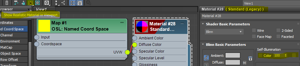
- Make “Named Coord Space” map and a Standard material.
- Make Self-Illumination 100.
- Connect UVW of “Named Coord Space” to the Diffuse Color of Standard material.
- Make sure to turn on Show Realistic Material in Viewport.
- Select “High Quality” mode in the viewport.
- Apply the Standard material to Mat.
 3dsMax OSL has an amazing OSL > HLSL auto conversion features as I posted before. You can see OSL map exactly same as render in viewport for most cases. All OSL map has a indicator at the bottom to show if this map could be displayed in viewport. To utilize this feature, your material must set to Show Realistic Material in Viewport, and your viewport must set to Advanced Rendering mode which High Quality preset has.
Your viewport should like this if you follow me correctly. What you are seeing is the World coordinate position as color. If you know what is World coordinate and Object coordinate, you can jump to the next section.
World position is the position from the world origin. Since we plug X, Y, Z, into R, G, B. You can see more Red color along X. Green along Y, Blue along Z. Color can only display from 0-1, that’s why you can only see a little gradient around an axis. Mat’s size is 8.2×1.0x9.4. If value is less than 0, it will be all black. If you rotate the model, you can see the color is not moving with object. Because the coordinate is fixed in world.
Another coordinate you might use is “Object” which is based on each object’s local coordinate. The origin will be at object’s pivot point. The axis will use object’s local axis. This means when the object is moving or rotating, the value will move with objects. If you need to make a map that is stick to the object, this is coordinate you need to use.
Now you know what World/Object position is and how to get the value with “Named Coord Space” map. Let’s utilize the value we got. We will try to blend 2 check map along the height(Z-axis)
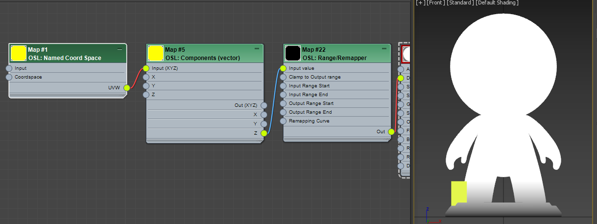
- Make a Maps > OSL > Math Vector > Component (Vector ).
- Connect UVW of Named Coord Space to Input of Component (Vector)
- Make a Maps > OSL > Math Float> Range/Remapper.
- Connect Z of Named Coord Space to Input Value of Range/Remapper
- Connect Out of Range/Remapper to Diffuse Color of the Standard material.
This should be what it looks like. BTW, I turned off AO. What’s happening here. We took only Z axis value with Component (Vector) map. This map is you can separate each channel from a vector or assemble a vector from 3 floats. Then, we fed the Z value to Range/Remapper which doesn’t do anything with default values. You can see the gradient goes from 0 to height 1. Again, as a color we can only visualize 0-1. I put 1 unit height box as reference.
Now we need to manipulate this value so the value can go from 0.0 – 1.0 between height 1.5 – 3.5. That’s what Range/Remapper does. Click the map and set Input Range Start to 1.5, Input Range End to 3.5. Now this map takes World Z position as Input Value. You can see “M” button shows that the value is coming from the connection, Then, map the input value 1.5 – 3.5 as 0.0 – 1.0 as output. You can visually see the gradient is moved up and 2x wider.

We can utilize this value as the Mix value for Mix map.Mix map is a map that Mix 2 color. Surprise! I could use Composite Map, too. But, this map is simpler. Also this is a tutorial. You gotta something new.
- Make a Maps > OSL > Math Color > Mix(Color) map.
- Make 2 OSL checker map with different colors and Size 0.05.
- Connect each Checker map as A and B of Mix(Color) map.
- Connect Out of Range/Remapper to Mix of Mix(Color) map.

Now let’s make it a little bit more complicated. What if I want to have blue check only top of Mat’s head like snow on his head. We can utilize normal for that.
You can get the normal data with Normal map. Duh. It is under Scene Attribute. It has one option, Coordspace. It should be “World”. Normal is “normal is an object such as a line, ray, or vector that is perpendicular to a given object.” according to Wiki. You can thin think as an arrow that coming out of a face. OK, that’s cool. But, so what? How can it help me?
Usually you need two sidekicks to utilize the Normal data, “Dot product” and another vector. Wha… WTH is “Dot poduct”? My head is already hurting!!! If you really want to know what it is. You can suffer from reading this. Butm I have a good news for ya. You don’t actually need to know what it is. We just need to know how to use this.
- Make a Maps > OSL > Math Vector > Dot product (vector).
- Make a Maps > OSL > Values > Vector Value.
Put 1.0 as Z value. Make sure X, Y are 0.0 - Make a Maps > OSL > Scene Attribute > Normal.
- Connect Out of Normal to A of Dot product (vector).
- Connect Out of Vector Value to B of Dot product (vector).
- Connect Out of Dot product (vector) to the Diffuse Color of Standard material.
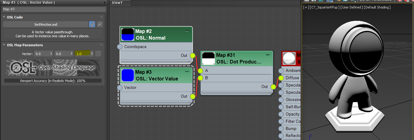
What did we just do? It looks like face becomes whiter if it face more to the top. When you dot product 3 vectors, Normal and [0, 0, 1] for us. The more 2 vectors look the same direction, The result becomes closer to 1.0. If two vectors are aligned exactly and toward same( direction. the dot product becomes 1.0. If two vectors are at right angle(90 degree), the dot product becomes 0.0. If two vectors are looking at the exact opposite direction. the dot product becomes -1.0. That’s all you need to know. This is how Falloff map works under the hood.
just for the test’s sake, change the vector Z value to -1.0. As you expected, it gets whiter as the point more face down.
 How about X = 1.0 and Y, X =0.0?

Got it? Then, Let’s set back to [0, 0, 1].
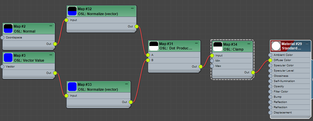
Now we need some house cleaning. When you dealing with normals and dot product. It is always a good idea to normalize the incoming vectors like this. this makes the incoming vector as a unit vector. If you don’t want to know what/why. just memorize and do it. It is good for you. Normal map is at Maps > OSL > Math Vector > Normalize (vector).
Another item for house cleaning is Clamp. As I mentioned above, dot product generates value from -1.0 to 1.0. You can not see the negative value in render or viewport since both only shows between 0.0 – 1.0. But, if you use negative value for other operation, it could cause issues, therefore. it is always a good idea to cut negative values with Clamp map. Clamp map limits any value outside of Min and Max value as Min and Max value. The default is 0.0 and 1.0. So, any value less than 0.0 will become 0.0. Any value bigger than 1.0 will become 1.0. The map is in Maps > OSL > Math Float > Clamp.
OK. Now we have 2 map trees. One for blending by height. Another one for the direction. We want to combine both so we can have blue check only at the top of Mat’s head. For this kinds of case, we can simply multiply two masks.
- Select Range/Remapper. Set Input Range Start to 3.0, Input Range End to 4.0.
This should move mas above Mat’s head. - Make a Maps > OSL > Math Float > Multiply map
- Connect Out of Range/Remapper to A of Multiply.
- Connect Out of Clamp to B of Multiply.
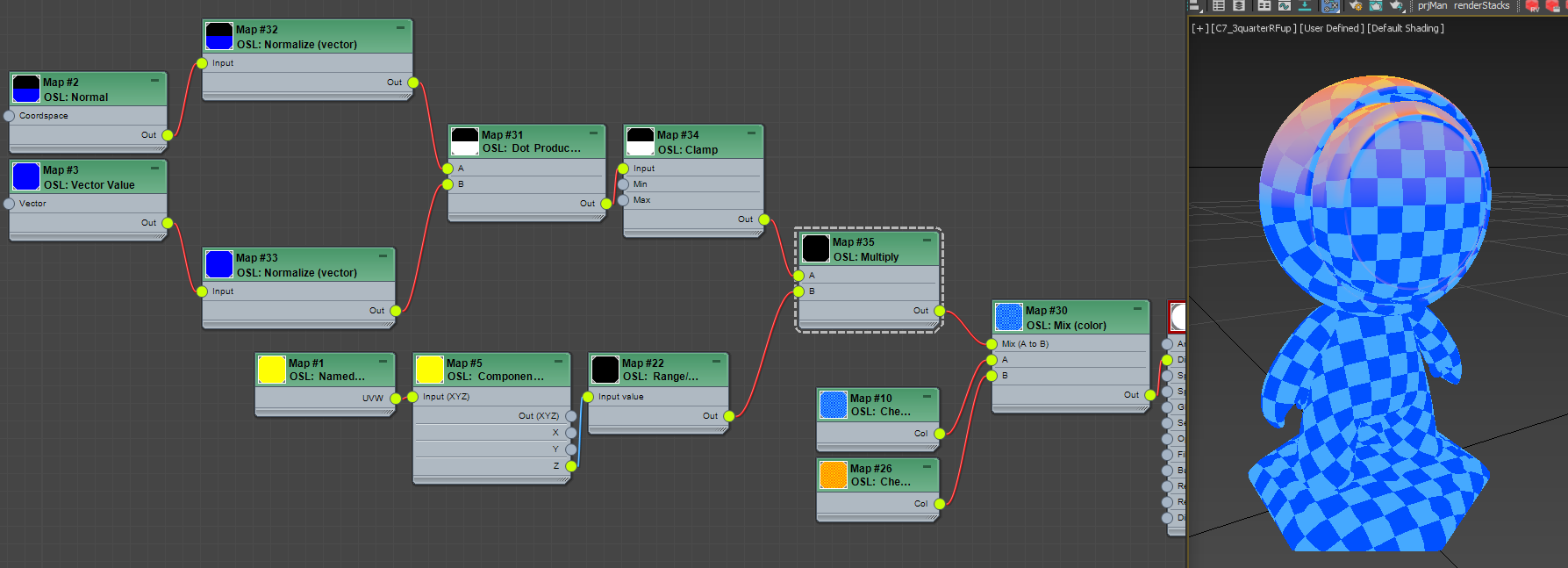
I know… after all those node, what you got is not that cool. But, this is how you learn.
In this tutorial…
- we learned how to get position and normal information from the scene
- how to utilize normal with dot product
- many of frequently used important math maps such as Range/Remapper, Clamp, Normalize, Multiply. Component.
BUT! Yes, there is always BUT!
The portion that we used to make a mask by face normal exist as one map, Falloff map. This map is basically same as the map tree we set up with a bunch of maps. It take cares Normalize and Clamp, it also have option to map ti the different range. It also allow to define each end as color which is same as Remapping the result with Gradient.
In Falloff map, you have coordinate to choose just like Normal map. You have Face and Away color for each end. Face means the color when dot product is 1.o. Away is the color when dot product is 0 because Type is Perpendicular/Parallel. If you switch to Toward/Away. The Color will map between dot product 1.0 to -1.0.

Thanks!