I’ve always wanted to create long-form 3dsMax courses, and now that I have some free time, I’ve decided to kick things off with the “Maxscript for Artists” course. The progress has been great so far, and it’s currently in the beta testing phase. That’s right, we’re actively beta testing the course!
I’m excited to introduce “Let’s 3dsMax” as the brand for all future courses, with “Let’s Maxscript” being the first. I hope to expand into courses like “Let’s DataChannel” and “Let’s OSL” in the future, and I’m even open to collaborating with other fantastic authors.
On that note, I’ve launched a pre-registration mailing list. If you join, you’ll receive a significant discount coupon once the course goes live!
I’m sure many of you already have used some form of pipeline or at least heard about it. Having a good pipeline could make your job easier, faster. It would reduce the burden of non-artistic tasks, and let you concentrate on making art.
If your studio is big enough to have dedicated TDs and engineers, you probably already have something. But, if you are a small team, the chances of having an automated pipeline would be low since it requires resources and effort. Or, simply you may not even know where to start.
I have had a chance to build a few pipelines from scratch and also have used a few existing pipelines, big and small. From those experiences, I want to share how I would build a new pipeline for a small team if I start again a small team.
Before we start, I just want to make sure that there is no “right” way for a pipeline. The best one is always the one that artists want/like to use, and every studio and every artist has their own taste. So, use this post as just a guide.
Does your studio have a rule for saving a max file and render outputs?
Let’s ask the first question. Does your studio have a rule for saving a max file and render outputs? If the answer is Yes. Then, you kinda already have a pipeline. You may not have an automated one. But, you certainly have a pipeline for sure. But, if it is not automated by code, a lot of benefits of having a pipeline will be lost. Humans simply can’t remember all those rules and execute the rules consistently all the time.
Consistency is the key for automation.
The first step for an automated pipeline can start from establishing a naming convention for project files and render output and making a tool for it.
Why? Because using a naming convention requires a minimum amount of coding. Sure, you can use custom DB or off-the-shelf solutions like ShotGun(Flow) or even xml/json. But, all these methods need to be coded and maintained by someone. If you don’t even have or can’t afford a TD, you probably can’t have a developer for this. Also, even when you could use these kinds of more advanced methods, it is good to have a solid naming convention.
Project folder and centralized storage
This workflow assumes everybody shares a central storage. In my 20+ years career, I never used project folders and have always used centralized storage. Considering a pipeline exists for multiple artists to work together, I’m not sure how the isolated project folder would work. So, this post assumes everybody has access to the same drive, either it is physically the same drive or synced.
Collect what kinds of information you need to define a task
Our goal is having a path and filename that would be unique per task.Then, we can add versions to the name. To get this, we need to collect what kinds of information is needed for a unique task. In this post, I’ll assume my studio is mostly working for episodic shows as an example.
To define a vfx task for episodic shows, you would need to know
Show name – The name of project or show like House, Airbender
Episode number – Usually you would combine season and episode as one entry
Shot name – each shot name
Task type – Is it modeling? Lookdev? animation?FX?
Task name – each task of a task type
You can add more entries like artist name(I usually don’t recommend) or 2 level task name, But, I would have it as simple as possible.
This also can work for a feature film or commercial, you can use the episode entry for sequence. If it is a simple commercial or music video. You can just leave the episode as “000” or something.
Again, Keep it simple and unified. Don’t try to have exceptions and conditions. Yes, in the end, code can deal with all kinds of exceptions and conditions. But, the more parts you have, the more chance you have problems.
OK. The theory itself is simple. But, actually establishing a rule is not that simple. There are a lot to consider. Let’s get into the details.
Parse-able Filename
The first rule of a naming for codes – Never ever use space in the name nor path. NEVER! Trust me just don’t do it. Life is easier without space.
That being said, we can start by simply assembling each entry with “_” for the filename. Something like this. Then, we can say that… “To get the information from the file name, split filename with _. Then, the first one is the show name. The second is the episode number, and on and on”.
HOUSE_201_24x56_FX_Explosion_v001.max
Assembling filename by a naming convention is easy. But, the name also need to be pare-sable by code. Basically, we should be able to extract back the information that assembles the file name. In that sense, adding “_” between each item is not enough. What if your client wants to use “_” in a shot name? Like “24_56”? Then, the filename becomes like this.
HOUSE_201_24_56_FX_Explosion_v001.max
Now filename parsing logic doesn’t work anymore because the 4th element from split would be “56”, not a task type. So, we need to have more complicated rules than just adding “_”. Good thing is that any code is very good at handling those complicated rules as long as the rule is clear and machine friendly. FYI, if you google “regex”, you can see what codes can do for parsing strings.
Let’s try a simpler logic. One of the common tool for establishing a naming convention is using special characters as separators to divide the filename into sections. Usually “_” and “-” are used for the separator because a lot of other special characters are an illegal character for a filename and path.
Now let’s think about which items we have more control over.
In my experience, there is a higher chance of possibility that clients could have their own naming convention for shots.
We have complete control over the task type since it is an internal stuff.
Usually project name and episode name could be a single word.
We need to have a good flexibility for the task name
With this requirement, this is what I did.
I used “-” as a main separator between task related items and others. So, I added “-” in front of the task type and decided not to use “-” in the task name. Then, we can say that “Separate filename divided at the last -”. Since the last “-” is the divider between task and else. You can use “-” in the shot name if you need. Something like this.
HOUSE_201_24-56–FX_Explosion_v001.max
Then, split the front part with “_” and take the first item as a show and the second item as an episode.
Task part is even easier, split the green part with “_”. Then, the first item is a task type, and the last is a version, and the anything inbetween is task name. You can use any alphabet, number and underscore fore task name.
A file path convention is easier than a filename convention since we just need to put each item at each level. But, there are a few extra things to consider compare to the filename convention.
First, you will need a root folder. That’s “Z:\Project”. Don’t make it too long or deep. Even tho we are making folders with code. The shorter, the better. Then, the show folder, “HOUSE”. Then, the episode folder, “201”. So far so Good. Easy.
But, what the heck is the “work” folder?
Currently we only have been talking about the project file, like max file and maya file, naming convention. But, you actually need a few different naming conventions for different things. For example, you can’t really use your max file naming convention for your render output. You will likely need more than one outputs, such as render element, from a max file. How about a published assets? If you build an asset publishing system, they will require a slightly different naming convention, “work” here means your working project files such as max and maya files, and we will put all project files under this sub folder.
Now you may wonder why under each episode? Why not under the show folder? Good question.
Your storage is expensive. You can’t store everything forever. At some point, you need to delete files. Even tho I do many things with scripts, I don’t really delete folders with scripts. You may think you made a perfect script for delete folders. But, imagine somehow your logic had a hole and all the project files for tomorrow delivery got deleted!
By having all your projects under the “work” folder under episode folder, you can clean up a project folder per episode easily. If you add this under show, you have to keep all projects for the show until the show ends or manually visit each episode and clean up. If you add it under the shot folder, you have to visit every shot to clean up projects files. Putting under episodes would be a happy medium.
We will talk later again. But, using the same logic, if we have “image” or “output” folder at the same level for render outputs and comps, you can clean up those folder first, and then clear projects later.
After “work”, continue just like file name, and the last folder would be DCC type or the project file format, and all versions for the DCC will be in the same folder.
Some might wonder why not have a folder for each version and have a DCC folder under there like this.
That kind of folder structure is usually for published assets which would have different formats for the same version all the time. For example, when you publish a model asset, you would publish an alembic file, a usd or a fbx along with your .max file. In that case, having the folder under the version folder would make sense.
But, usually you wouldn’t switch program between versions. If you ever need to switch to other program, you can just restart from v001.
OK, let’s see what we have again. This is the full path that I’m using.
This_is_Your_Explosion – task name(alphanumeric & any number of underscore)
max – each program identifier
Project Manager Tool
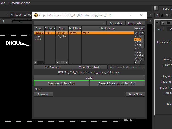
Now we have a rule. Next, we need a tool. Because the consistency of the data is key for pipeline automation. As I said in the beginning, No human can remember these rules and execute correctly all the time. Only way to make this work is having a tool. Something like this.
The tool hides the rules and the naming convention from artist and allow to browse the project easily.
Allows to load/version up their project. When the version is up, it will automatically version up to the latest.
Allows to create new task, and convert the current scene as the first version.
Allows to add/edit notes.
Remembers the history of project file load/save and allow to quickly select from history.
These list is just a start. Since you have a way to browse set the context of task. You can add more and more features to this tools. For example…
The time logging could be integrated into this UI or even automate it by detecting the file being opened.
Could have an easy shortcut to open folders for the chosen task.
Could display Flow(ShotGrid) notes for the task.
and more and more.
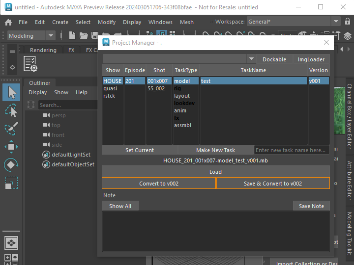
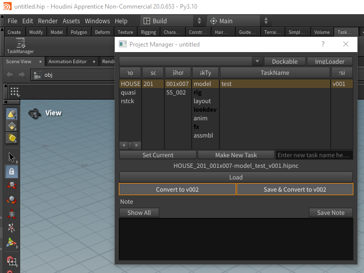
Thanks to the fact that most programs are now supporting Python. You can build the interface once and reuse it for many programs. You can see my example tool is working in Maya, Houdini, Nuke even for Photoshop.
Expand The Naming Convention to Renders
After the project file name convention and tool are sorted out, the next stop would be the render output file name.
For render output, we need to extend upon the project file naming convention so we can automatically track where the renders are coming from.
This is an example of render output file path and name convention.
I changed “work” to “render3d” so you can have a render3d folder per episode. With this, you can delete render outputs first after a project is done while keeping project files.
You would have multiple outputs from a project file. Usually we call them “pass”. So, I added the pass folder after the task name folder.
I used “-” as a separator so I can use “_” in the pass name if I need.
Then, we need the version folder since you will likely output an image sequence. It is always a good idea to have only a sequence in a folder.
Then, you have the exr sequence file in the version folder. For frame number padding I would recommend to use “.” as a separator than “_”.
NOW here is a little bit controversial part, render elements(AOV). If you are using the multi-channel exr workflow. You wouldn’t need a render element sub folder. I personally am not a big fan of putting all channels in a gigantic exr file.
If you are using the split file workflow, you also need to add a render elements folder. As I mentioned once, it is always better to be consistent. So, I would have the RGB element in its own folder. But, some may opt to leave RGB in the version folder and only have other elements in their own folder.
If you decide to have AOV folders, here is one more thing you might think about. You can swap the position of the AOV folder and the version folder like this.
This makes deleting unnecessary AOVs easier since all versions for a pass are under a folder and. it is easier for a code to pull all the versions list. But, this also makes it harder to know what is the highest version of all to determine the next version, and deleting certain version becomes more difficult.
OK, now one last thing I need to talk about render output is how to decide the version number. Obviously the simplest method would be to keep versioning up for every render submission.
Another way of versioning is syncing the output version number to the scene file version number. For example, , If your scene version is v008, your render output also becomes v008. It is possible because the render output naming convention has all the items of the project file naming convention. There is no chance that different max files could generate the same render output.
If you do this, you have to version up your scene file to get a new version of renders. This also means you will have skipped versions. That sounds bad. Why would you do this then? Because it allows you to easily track where your renders come from without any extra system. If you automate max file version up after submitting render, you can always go back to the version of max file when you need and get exactly the same render again.
renderStacks to the rescue
Now you need a tool to set the render output path automatically. Yes, right. This is the moment that you need renderStacks. 🙂
In the following picture, you can see I just made a global function and feed it as maxscript token for rednerStacks. Now you never need to type render output path ever. renderStacks will automatically set the render output path every time when you submit or render.
Of course, you can use any other script/tool, too. The point is that you must have a tool to set it.
Comp/PreComp/Plates
Now you have a naming convention for project file and render output and have a tool to handle those path. Then, we can say you have a MVP(Minimum Viable Product) pipeline. But, if your workflow requires comps most of the time. Then, you would like to have naming conventions for comp and precomp as a next step.
This was the project file naming convention for max.
For 3d projects, it made sense to have lookdev, fx, and animation task types. But, for comp, do you need them? Do you have a comp for fx and a comp for lookdev? Probably not…
Then, what should we do with the task type? We can remove the item from file and path name convention. That means you would need a separate naming convention for comps which means it will cost more to develop and maintain while having more chances to have a bug. As I mentioned a few times, it is always better to be simple and consistent.
Therefore, I would keep the task type. But, I would change the items. We can at least have a “comp” task type. How about the task name? Usually you would have 1 comp per shot. But, you never know if you would need more than 1 comp in the future. What if the director wants to have 3 options! Since we already have it in the naming convention, it is better to keep it consistent and flexible. But, we can have a soft convention to agree to use “main” as a default task name.
Now here is something to think about. How about other support task like precomp or roto? If it is for precomp for the same nuke file. It could be just another “pass” like 3d render. But, if it needs its own nuke file, you have 2 choices. 1) having its own task type 2) using a task name.
If you decide to have its own task type such as “precomp” or “roto”, you will have one more level of flexibility( task name + pass name). It also means precomp or roto will have their own sub folders which means it will be easier to clean up. But, you will have a lot of empty or folders with only one sub folder.
Or, you can just utilize the task name. Just make sure artists use “precomp_” or “roto_” prefix or build a tool that can force it.
Lastly, I would separate the comps from the 3d renders. Something like under “image2d”. Our final comp/precomp file naming convention will be like this.
main– is output name from a comp project file. If you are using Nuke, this would be your Write node name.
Of course, you should never generate this path manually. For local rendering, you would make own render dialog with automatic path update. For network render, you would a code to update Write nodes version to latest before open network render submission dialog.
Happily ever after
After you implement a good naming convention and tools, you can start to take an advantage of the consistent and predictable structure of files. For example, this is the image loader for my project manager. It build the list of all image assets(render3d, comp, precomp)
This is a Nuke Read node updater.
Assets, Caches and Beyond
If you want to go further, you can start to explore a pipeline for asset publishing. I wish continue this tutorial to cover asset publishing. But, unfortunately, everybody works differently, and it is hard to make a universal solution without bloat.
But, I have a few cents that I can share from my experience.
Start from the simplest asset. Usually the camera publishing is the best candidate. The data is small, and it is such an essential.
The next would be the cache or proxy that you would use most often. If you use Phoenix, that would be a good candidate.
The best pipeline is just automating what you have done. Do not try to force what you saw or heard from the internet. Again, each company has own way of working. Do not try to change it. Try to improve it.
Don’t try to do too many thing too fast. In terms of pipeline, the stability is more important than features. If artist can’t trust the pipeline, they will try to avoid it and work around it.
OK! That’s it. Now you know where to start to build your awesome pipeline. I think I put enough information in this post. But, if you think you need help or just want to use what I have built. Contact me through LinkedIn message. I’m available for consulting. 🙂
Substitute modifier is one of the most underrated modifiers in 3dsMax and one of my favorite modifiers. As the name suggests, this modifier replaces the object’s mesh/poly. How to use is very simple. Just apply the modifier, turn on “Pick Scene Object” button and pick an object in the scene to substitute.
You can choose to use the substitute mesh only for viewport or render.
You can also choose to use an object from another max file.
We can think about a few useful situations such as…
I already have a big stack and animation started from Box. Now I wanted to start from ChamferBox instead of Box.
I can substitute highres objects with low res ones only for viewport to make viewport faster.
I can have low res placement holder objects in the scene and substitute with highres objects in another max file.
You can have multiple versions of mesh in an object while keeping all the connection to other portions of 3dsMax.
BUT! That’s not all. Substitute modifier has more super powers.
It automatically disables the evaluation of all the modifiers under it
It makes sense since the Substitute modifier provides a mesh from the stack point. Whatever at the below of the stack doesn’t do anything in any way. The best part is that you don’t have to set anything manually. This modifier just does it. Combined with the feature that allow to use Substitute modifier only for viewport display, this provide a great work around to improve the scene performance when you have a lot of hires animated meshes.
For example…
if you substitute an animated tree with a static low res tree, this modifier blocks the evaluation of animation.
If you have an animated alembic cache object, this modifier will stop loading the alembic file every time when you scrub through. In the following image, I snapshot a frame and used that for display using Substitute modifier. You can see alembic object stopped loading the cache file.
Turn off VRayVolumeGrid preview which will load files and update every frame. Make a preview mesh and use Substitute modifier to display it. This will allow you to directly place vdb without waiting for every singler cache file loading.
It can embed the replacement mesh data in the modifier
This is a really really powerful feature. After you pick an object from the scene, you can delete the object. Then, the modifier will hold the mesh information in itself which essentially act as a cache modifier.
This means that you can collapse the stack while keeping all the history. l Some of you probably have been duplicating objects and collapse in the scene and save a copy in another max file for future use. You don’t need to do that any more. Everything can be just stored in the same scene
one of the benefit of caching a big stack is to improve max file loading time. I want to cover this topic in depth some day. In short, 3dsMax file doesn’t save the result of stack in the .max file. If you make a Box and apply Bend modifier. 3dsMax just stores the class(Box, Bend and its parameters. Then, when the file is loaded, it evaluates all the classes and generates a mesh. This means if you have very big stack or very calculation intensive modifiers. The file opening can take a long time. That’s why some modifiers like Boolean, Conform or Retopology have own caching mechanism. With Substitute modifier, you can cache any objects with modifier in the scene if you want. Obviously, it has a trade off. It will increase the max file size. You gotta pick your poison.
Another benefit is that it can be used as a countermeasure for possible mesh corruption. As a procedural evaluation system, if anything goes wrong in the middle of the stack, the above of the stack would produce an unwanted result. For example, Edit Poly is an awesome and powerful modifier. But, it can be fragile with certain operations. In fact, Edit Poly never stored the result of change in the modifier. It is actually a mini stack in a stack. It stores every operation you did and re-execute then you open the file. So, even tho it is slim, there is a chance that one of hundreds of operations, especially one that removes or adds sub-objects, could go wrong. For that case, you can use Substitute modifier to lock/freeze the status of stack.
csStackCache
So, I made a small script called csStackCache to take advantage of Substitute modifier’s super power. You can find from csTools > csStackCach in the Customize UI dialog.
How to use is simple.
Select objects that you want to cache.
All – all geometry objects
Selection – Selected objects
Selection Set – the chosen selection set
Press “Cache”. This script will add a Substitute modifier named “csStackCache” just above of the first viewport enabled modifier. In the following image, It is added under TurboSmooth because it was set to Off in Viewport. If you already had “csStackCache”, it will use the position. So, if you need to add “csStackCache” at certain position. Use the “Add Cache” button to add and move around it. Then, Cache them. For example, if you have any animated modifiers, you will need to cache blow the modifiers. If you cache above them, it will freeze animation.
If you want to remove “csStackCache”, select objects in the same way and pres “Remove Cache
This is a full procedural setup with some of the new additions of #3dsMax in recent releases such as Array modifier, Boolean modifier and Subdivide modifier. Especially, the new OpenVDB based boolean opens up so many new possibilities.
I originally planned to release a sample pack for Boolean modifier. But, somehow this video has gotten so much response. I decide to release this scene file first.
Nowadays “proceduralism” is a very hot trend. Yet many 3dsMax users don’t realize that 3dsMax has had a wide range of procedural features for decades. One of the not-so-well-known procedural features is Data Channel modifier which was introduced in 2017!.
A few days ago. I saw a question about how to make this animation on the tyFlow Facebook group. It was a perfect example of what DCM can easily do with a simple setup. Now with Array modifier, it took 5 min for me to put it together.
1. Let’s start with a box. I guess I don’t need to explain more. 🙂
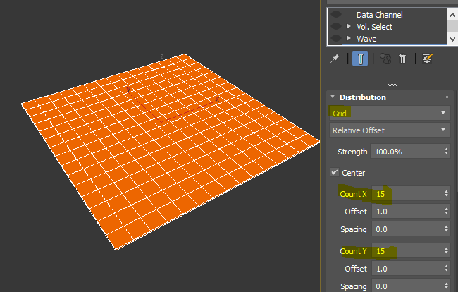
2. Then, 15×15 Grid Array.
3. Then, Wave modifier. I rotated the gizmo 45 drgree.
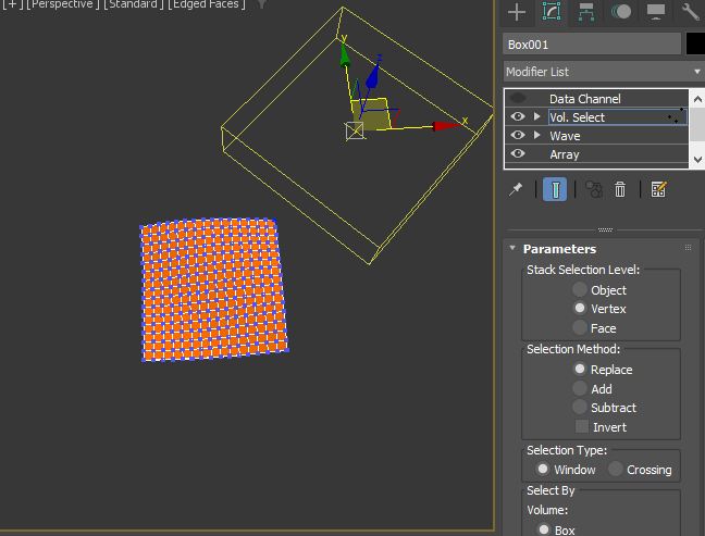
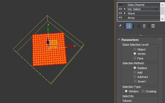
4. Then, I applied Vol.Select. Rotate the Gizmo 45 degree again and moved out of mesh.
5. Then, animate the gizmo to select all vertex on the verts. This is frame 36.
Frame 72.
As you can expect, Ill drive the scale animation of each element with animated soft selection using Data Channel modifier. Apply Data Channel modifier.
6. Apply Data Channel modifier.
7. Click “Add Operator” button.
8. Add “Transform Elements” and “Vertex Output”
9. Transform Element modifer allow you to transform(move, rotate, scale) each element using a selected channel. For this setup, we will use soft selection channel as a driver. Set “Input Channel” as Soft Selection.
10. Set Transfrom as “Scale %(Uniform)”. Leave everything as is. It should look like the following image.
This setup means, DCM will scale each element from 0 to 100% using soft selection value 0-1. So, if the average of soft selection value of an element is 0. The element will be scale to 0. If the average is 0.5, it will be half size(50&), of the average is 1.0, it will be full size(100&).
11. Select “Vertex Output” and set Position/Replace. The Transform Element generates transformed vertex position data for each vertex and store in a vertex channel and pass down. We need to replace vertex position channel with the new vector channel to see the animation. “Vertex Output” operator is doing that,
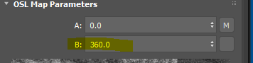
12. If you want to make it more interesting, you can add one more Transform Elements for rotation. Make sure to right click the second Transform Element and change to “Replace” since you are adding a new separate channel. If you choose “Add”, the value will be added to the vector channel coming from the above “Transform Element”.
13. Set “Transform” to “Rotation” and set all “Max” value to 360. So, you can do a complete turn.
We, 3dsMax users, love 3rd party scripts and plugins. But, we don’t necessarily like the process of installing and managing those. Sometimes this is one of the reasons why we don’t even upgrade 3dsMax. In this post, I’ll show you how to decouple the installation of 3rd party scripts from 3dsMax for easier management. I will also show how the new pipeline integration feature in 3dsMax 2022.3 will make this task simpler. We will use the famous Soulburn script as an example.
First, we need to know how scripts are loaded when 3dsMax launches. Fortunately there is already very good documentation here. In a nutshell, 3dsMax executes startup scripts and macros scripts from certain locations while being launched. Users need to install scripts in those locations so they can be loaded properly.
Startup scripts
There are a few reasons why users would want to execute scripts automatically when 3dsMax starts. For example, If you use any scripted plugins such as the famous Paul’s PEN_Attribute_Holder, you probably want it to be loaded and ready to use just like C++ plugins. Another important use of startup script is setting working environments, defaults and system directories which we will utilize in this post. I also have a separate post about this subject here. Please check it out.
As you see in the above document, 3dsMax reads the startup script from the various places. But, the most commonly used folders are these two folders.
system startup scripts folder – C:\Program Files\Autodesk\3ds Max 2022\scripts\Startup
user startup scripts folder – C:\Users\[username]\AppData\Local\Autodesk\3dsMax\2022 – 64bit\ENU\scripts\startup
One of the important rules of 3dsMax tool management is you never touch the 3dsMax root folder. If you need to add/modify anything, you should add/modify files in the appdata folder which is usually called the “ENU” folder. C:\Users\[username]\AppData\Local\Autodesk\3dsMax\2022 – 64bit\ENU\
But, as you can see, using a user data folder brings a lot of challenges, especially for a team. So, I have been managing startup scripts using a seed startup script, [3dsMax root]/scripts/startup.ms. This script basically calls the real script like this.
By using this seed script, I can update the startup script centrally without re-depolying again to all workstations. this is one of two files I allow an exception personally.
BUT! I don’t need this seed script anymore because of the new pipeline integration feature. This feature allows users to set various paths used by 3dsMax with Environment variables which means you can set paths from the outside of 3dsMax before it launches. Even though 3dsMax provides a great amount of control over every aspect of 3dsMax with Maxscript. The fundamental limitation of the script based approach is that everything happens after 3dsMax launched. The new pipeline integration removes this limitation. Also it allows you to control folders that never have been allowed to control before such as the appdata folder itself.
So, how can we use this feature? There are 2 ways to set environment variables in Windows.
The second way is using a batch file or Python to set env var only for the session. If your studio is using a launcher, they are already using this way.
For startup script, we can use the first method since scripts are usually compatible between 3dsMax versions and you can put a condition if there are any version specific things in it.
After I added “ADSK_3DSMAX_STARTUPSCRIPTS_ADDON_DIR” env var, my 3dsMax runs any scripts in this folder. I don’t need to add anything to 3dsMax root folder. I don’t need to worry about re-coying again this file after wiping out ENU folder to solve my 3dsMax issues. I don’t even need to do anything for any future version of 3dsMax. It is truly set it and forget it!
Setting custom system directories with startup script
Even though the new pipeline integration allows you to add “scripts” folders with “ADSK_3DSMAX_SCRIPTS_ADDON_DIR”. This folder actually doesn’t matter much because we never execute all scripts in these folders automatically. Also setting env var doesn’t actually change 3dsMax system directories, and most scripts are usually called other scripts or macroscript(We will discuss it later) using #scripts or #userScripts system directories to allow more flexible installation instead of hard-coded path. For example, this is a macroscript from the Soulburn script.
MacroScript blendedBoxMapMaker category:"SoulburnScripts" tooltip:"blendedBoxMapMaker" Icon:#("SoulburnScripts_blendedBoxMapMaker",1)
(
Include "$scripts/SoulburnScripts/scripts/blendedBoxMapMaker.ms"
on execute do blendedBoxMapMakerDefaults()
on Altexecute type do blendedBoxMapMakerUI()
)
As you can see, this action will try to find “/SoulburnScripts/scripts/blendedBoxMapMaker.ms” file under #scripts folder($scripts is a symbolic pathname for #scripts).
By default #scripts is set to C:\Program Files\Autodesk\3ds Max 2022\scripts and #userScripts is set to C:\Users\ChangsooEun\AppData\Local\Autodesk\3dsMax\2022 – 64bit\ENU\scripts. 3rd party scripts are suppose to use #userScripts. This means that we have to install the Soulburn script files under C:\Program Files\Autodesk\3ds Max 2022\scripts unless we change the location.
The good news is that we can change any system directories using the “setdir” Maxscript command! This is the first two lines of my startup script. This allows me to install any 3rd party script under D:\PROJECT\_maxDefault\scripts\ instead of 3dsMax root or my user folder.
TIP! As you can see from the 3dsMax system directories document, you can also set any project folders using “setdir” command. By default, they are set as a relative path to the current project folder. But, you can change those using “setdir“ command. For example, you can change autoback folder to “D:\3dsMax_Autoback” instead of in your Document folder.
setdir #autoback @"D:\3dsMax_Autoback"
Macroscripts
Macroscript is a script that defines “ActionItems” in 3dsMax. ActionItem is “that represents the action that can be assigned to Toolbars, Menus, QuadMenus and Keyboard Shortcuts using the Customize User Interface dialog”. Basically if you want to make an UI like a button or shortcut, you need a macroscript for the script. It also allows the script to show up in Global Search(X menu).
3dsMax executes the macroscripts in #userMacros and #macroScripts system directories by default when it starts. Now you may think we could change these folder to own custom folder like #scripts and #userscripts. BUT! We can’t do that for macroscript because 3dsMax and many 3rd parties actually use these folders. BTW, there is the new Autodesk Application Plug-in Package format which 3rd parties can completely separate their files from 3dsMax factory installation. If your favorite plugin doesn’t support this. Ask them!
Another problem of #userMacros folder is that it is used when user create macroscript by drag and drop. For example, if I type print “Hello, World” and drag and drop this line to a toolbar. 3dsMax makes “DragAndDrop-Macro1.mcr” under #userscripts folder. If you share this folder across many users, you will get macroscript from all your teammates.
Therefore, it is better to load the commonly shared macroscripts from an added folder using “ADSK_3DSMAX_MACROS_ADDON_DIR” env var.
If you are using 3dsMax without the pipeline integration, you have a few ways to do this.
Copy all .mcr files to #userMacros folder.
Just run all .mcr files with the “FileIn” function.
You can copy to the 3dsMax root folder. But, I wouldn’t recommend it.
Honestly none of the above options are good. This just shows how beneficial the new pipeline integration is.
Icons
This is the last piece of puzzle for 3rd party script management. Sometimes 3rd party scripts include icon files. We can use both startup script or env var for this. It doesn’t matter much. I choose to use “ADSK_3DSMAX_ICONS_ADDON_DIR” env var.
If you are using older version of 3dsMax, I will just set #usericons folder in a startup script.
Let’s put together all the pieces for Soulburn script
If you download the SoulburnScriptsPack_3dsMax_v112_R2013toR2022.zip file, it has 3 folders.
Copy all files in “MacroScripts” folder to D:\PROJECT\_maxDefault\usermacros (ADSK_3DSMAX_MACROS_ADDON_DIR)
Copy “SoulburnScripts” folder in “scripts” folder to D:\PROJECT\_maxDefault\scripts\ (#scripts)
Copy all files in “\UI_ln\IconsDark” or “\UI_ln\Icons” folder to D:\PROJECT\_maxDefault\usericons (ADSK_3DSMAX_ICONS_ADDON_DIR). You can’t use “Icons” or “IconsDark” folder in #usericons folder. .bmp icons are only supported for backward compatibility since 3dsMax 2017. If you want to have a different set of icons per theme, you need to use the new .png icon naming convention and “iconname:” argument. The details are here.
Now I have the Soulburn script in my 3dsMax 2021, 2022 and will have them in the whatever future version of 3dsMax without any more steps. I can nuke the ENU folder anytime without worrying about re-installing these scripts.
This also works with any 3rd party scripts.
If they are .mcr files, put in the ADSK_3DSMAX_MACROS_ADDON_DIR folder.
If they are .ms files, put in the #scripts folder.
If they have icons, put in the ADSK_3DSMAX_ICONS_ADDON_DIR folder.
To help your understanding, I’ll give one more example, another famous script, DebrisMaker2.
In this case, the downloaded file is .mzp file. This is a self-installation zip file. You can actually unzip with any zip uncompressor such as 7-zip.
If you unzip, it has 3 folders under “DebrisMaker2.0” folder. Guess where would you need to copy the files?
MacroScripts -> D:\PROJECT\_maxDefault\usermacros
Scripts -> D:\PROJECT\_maxDefault\scripts\
UI_ln\Icons -> D:\PROJECT\_maxDefault\usericons
Again, now you will have DebrisMaker2 in any 3dsMax 2021 and above!
Before I finish this post. Someone might wonders why I said “3dsMax 2021 and above”. Isn’t it a new feature of 3dsMax 2022.3? Yes, right. It is officially added to 3dsMax 2022.3 with more complete support. But, 3dsMax 2021.3 actually have had some env var support for Autodesk internal use. At least, the 3 env var we have utilized work for 2021.3, too. I let you know because setting env var as system env var will affect 2021.3. I don’t want you to be confused or surprised.
If you want to use the pipeline integration for only certain version of 3dsMax, you have to use batch file of Python script which I will cover in the next post.
I made this DCM(DataChannel Modifier) while ago to help my friend’s shot. I thought that it might be worth as my first DCM mini tutorial. So, here we go!
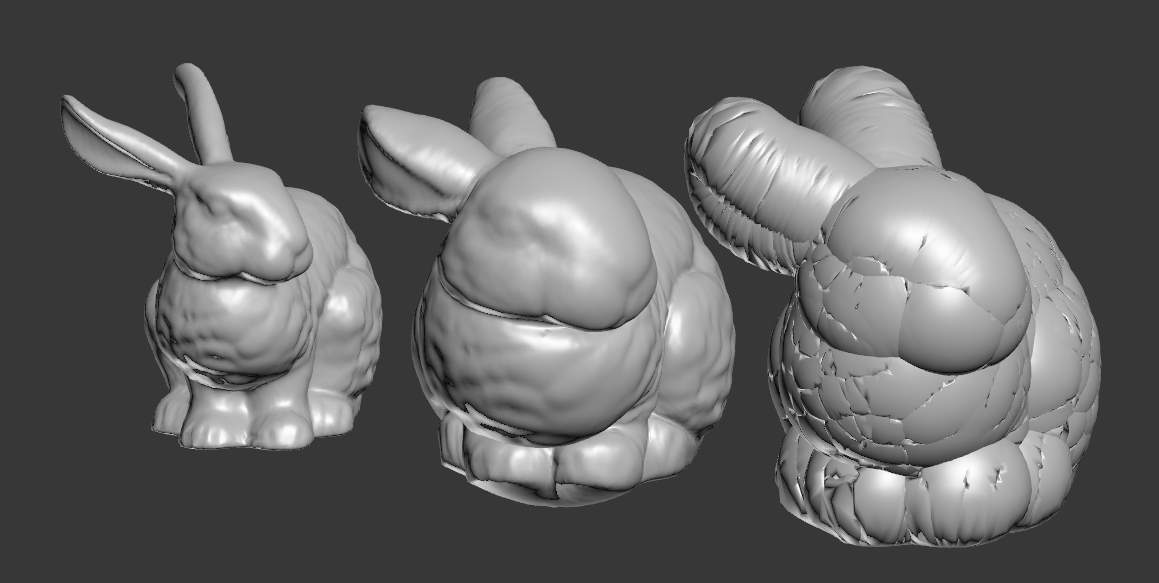
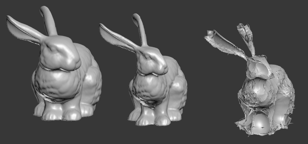
Let’s see the following picture. This is the famous Stanford Bunny model. Left is the original shape. The right is 3dsMax Push modifier. As you can see, when you push a lot the faces start to overlap. The middle is the result of “Smooth Push” which is a simple DCM setup. As you can see It pushed it, but it pushes more gently(?).
How Push modifier works is really really simple. It moves each verts along the its normal by the given amount. As you can see, Push modifier only has one parameter which is the distance the verts are moved along normals.
Becase the verts move along the normal, verts will meet each other if you have concave shape. To prevent that, I simple smooth or blurred or relaxed the normals and used that. Let’s see how that translate to DCM setup.
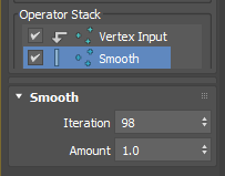
First, we need to get vertex normal for each verts.
Click “Add Operator”
Add “Vertex Input”.
Choose “Average Normals”.
As an Input operator, Vertex Input allow you to grab various data from each verts. The 3 dot icon in front of operator name indicates, you are processing vertex data.
Next, Add “Smooth” operator from Process operators. It has 2 values, Iteration and Amount just like Relax modifier. The bigger Iteration and Amount is, the the smoother result you will get. This operator will make more gentle normals by averaging normals with neighboring normals just like blurring an image.
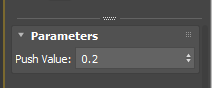
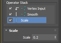
Now we need to have a way to control amount of Push. This is simple. Let’s add “Scale” operator from Process operators. This operator multiplies the given value to float or vector. If the value is 1.0. The size of normal doesn’t change. If the value is 1.0, you ar making normal bigger. If the value is less than 1.0, you are making normal smaller. This is exactly what “Push value” in Push modifier does.
What we have now in the current Data Channel is the offset vector of the each vertex. So, you need to add these vectors to the original vertex position.
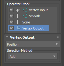
Add Vertex Output operator from Output operators.
Choose “Position” as output channel.
Change “Selection Method” from “Replace” to “Add”, which means you will add the current channel data to the existing vertex position data.
Welcome to my 3rd OSL tutorial! In this tutorial, we well learn how to query scene/object data and utilize it with MATH! Yes, you heard it right. MATH! I know you always have been regretted that you didn’t pay attention to the math class when you were in middle school. But, never late than never. Re-learning some simple math will make your life easier. WE CAN DO IT TOGETHER!
Like always, we will not write a single line of code in this tutorial. We will use SlateME as our OSL editor. Let me say it again, YOU DON’T NEED TO KNOW HOW TO CODE TO USE OSL IN 3dsMax.
First, let’s see how we can query the position of pixel in the scene and utilize. For example, we can make a transition of 2 maps between certain heights from the ground.
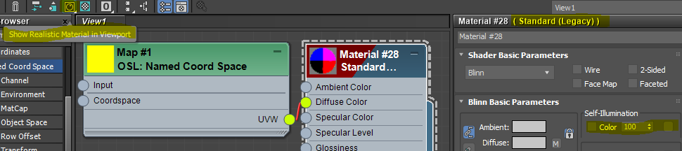
You can use “Named Coord Space” map to get a position of a coordinate space.Let’s make one and s some basic setup for the tutorial.
Make “Named Coord Space” map and a Standard material.
Make Self-Illumination 100.
Connect UVW of “Named Coord Space” to the Diffuse Color of Standard material.
Make sure to turn on Show Realistic Material in Viewport.
Select “High Quality” mode in the viewport.
Apply the Standard material to Mat.
3dsMax OSL has an amazing OSL > HLSL auto conversion features as I posted before. You can see OSL map exactly same as render in viewport for most cases. All OSL map has a indicator at the bottom to show if this map could be displayed in viewport. To utilize this feature, your material must set to Show Realistic Material in Viewport, and your viewport must set to Advanced Rendering mode which High Quality preset has.
Your viewport should like this if you follow me correctly. What you are seeing is the World coordinate position as color. If you know what is World coordinate and Object coordinate, you can jump to the next section.
World position is the position from the world origin. Since we plug X, Y, Z, into R, G, B. You can see more Red color along X. Green along Y, Blue along Z. Color can only display from 0-1, that’s why you can only see a little gradient around an axis. Mat’s size is 8.2×1.0x9.4. If value is less than 0, it will be all black. If you rotate the model, you can see the color is not moving with object. Because the coordinate is fixed in world.
Another coordinate you might use is “Object” which is based on each object’s local coordinate. The origin will be at object’s pivot point. The axis will use object’s local axis. This means when the object is moving or rotating, the value will move with objects. If you need to make a map that is stick to the object, this is coordinate you need to use.
Now you know what World/Object position is and how to get the value with “Named Coord Space” map. Let’s utilize the value we got. We will try to blend 2 check map along the height(Z-axis)
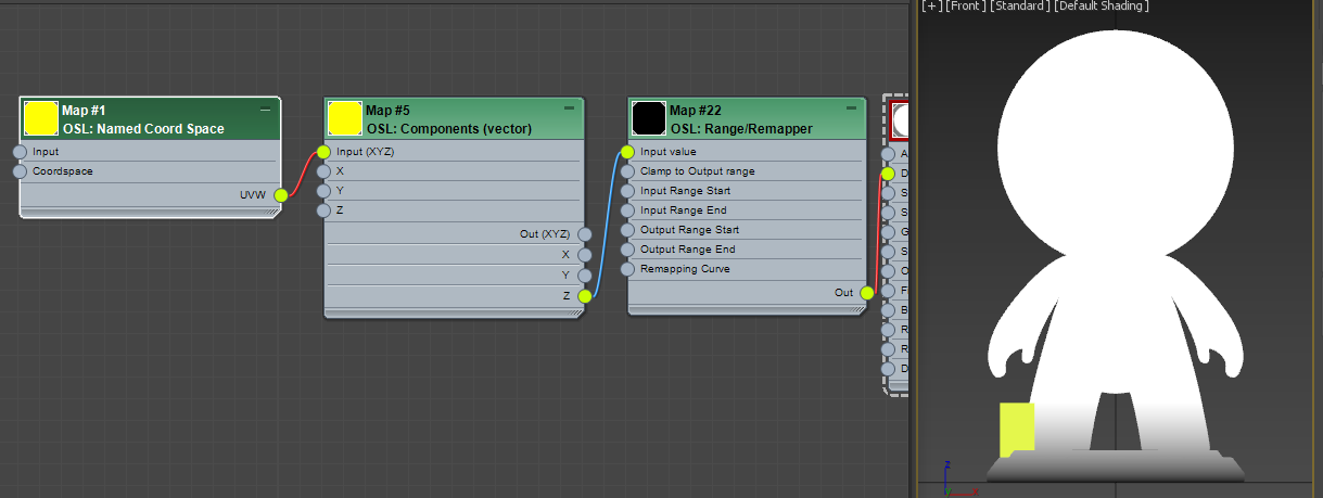
Make a Maps > OSL > Math Vector > Component (Vector ).
Connect UVWof Named Coord Space to Inputof Component (Vector)
Make a Maps > OSL > Math Float> Range/Remapper.
Connect Z of Named Coord Space to Input Value of Range/Remapper
Connect Out of Range/Remapper to Diffuse Color of the Standard material.
This should be what it looks like. BTW, I turned off AO. What’s happening here. We took only Z axis value with Component (Vector) map. This map is you can separate each channel from a vector or assemble a vector from 3 floats. Then, we fed the Z value to Range/Remapper which doesn’t do anything with default values. You can see the gradient goes from 0 to height 1. Again, as a color we can only visualize 0-1. I put 1 unit height box as reference.
Now we need to manipulate this value so the value can go from 0.0 – 1.0 between height 1.5 – 3.5. That’s what Range/Remapper does. Click the map and set Input Range Startto 1.5, Input Range End to 3.5. Now this map takes World Z position as Input Value. You can see “M” button shows that the value is coming from the connection, Then, map the input value 1.5 – 3.5 as 0.0 – 1.0 as output. You can visually see the gradient is moved up and 2x wider.
We can utilize this value as the Mix value for Mix map.Mix map is a map that Mix 2 color. Surprise! I could use Composite Map, too. But, this map is simpler. Also this is a tutorial. You gotta something new.
Make a Maps > OSL > Math Color > Mix(Color) map.
Make 2 OSL checker map with different colors and Size 0.05.
Connect each Checker map as A and B ofMix(Color) map.
Connect Outof Range/Remapper to Mix of Mix(Color) map.
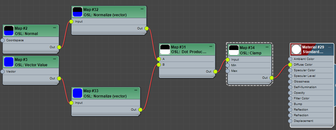
Now let’s make it a little bit more complicated. What if I want to have blue check only top of Mat’s head like snow on his head. We can utilize normal for that.
You can get the normal data with Normal map. Duh. It is under Scene Attribute. It has one option, Coordspace. It should be “World”. Normal is “normal is an object such as a line, ray, or vector that is perpendicular to a given object.” according to Wiki. You can thin think as an arrow that coming out of a face. OK, that’s cool. But, so what? How can it help me?
Usually you need two sidekicks to utilize the Normal data, “Dot product” and another vector. Wha… WTH is “Dot poduct”? My head is already hurting!!! If you really want to know what it is. You can suffer from reading this. Butm I have a good news for ya. You don’t actually need to know what it is. We just need to know how to use this.
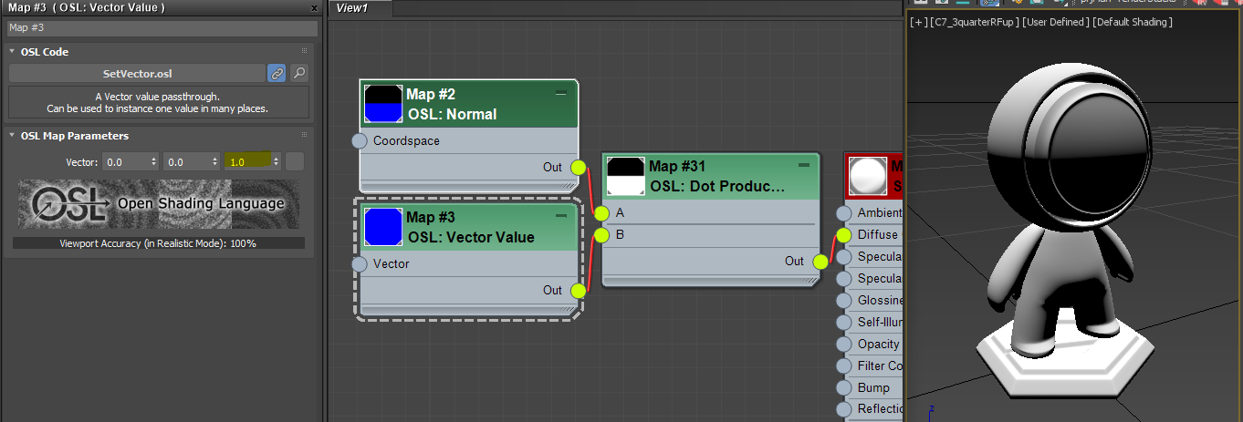
Make a Maps > OSL > Math Vector > Dot product (vector).
Make a Maps > OSL > Values > Vector Value. Put 1.0 as Z value. Make sure X, Y are 0.0
Make a Maps > OSL > Scene Attribute > Normal.
Connect Outof Normal to Aof Dot product (vector).
Connect Outof Vector Value to Bof Dot product (vector).
Connect Outof Dot product (vector) to the Diffuse Color of Standard material.
What did we just do? It looks like face becomes whiter if it face more to the top. When you dot product 3 vectors, Normal and [0, 0, 1] for us. The more 2 vectors look the same direction, The result becomes closer to 1.0. If two vectors are aligned exactly and toward same( direction. the dot product becomes 1.0. If two vectors are at right angle(90 degree), the dot product becomes 0.0. If two vectors are looking at the exact opposite direction. the dot product becomes -1.0. That’s all you need to know. This is how Falloff map works under the hood.
just for the test’s sake, change the vector Z value to -1.0. As you expected, it gets whiter as the point more face down.
How about X = 1.0 and Y, X =0.0?
Got it? Then, Let’s set back to [0, 0, 1].
Now we need some house cleaning. When you dealing with normals and dot product. It is always a good idea to normalize the incoming vectors like this. this makes the incoming vector as a unit vector. If you don’t want to know what/why. just memorize and do it. It is good for you. Normal map is at Maps > OSL > Math Vector > Normalize (vector).
Another item for house cleaning is Clamp. As I mentioned above, dot product generates value from -1.0 to 1.0. You can not see the negative value in render or viewport since both only shows between 0.0 – 1.0. But, if you use negative value for other operation, it could cause issues, therefore. it is always a good idea to cut negative values with Clamp map. Clamp map limits any value outside of Minand Maxvalue as Min and Max value. The default is 0.0 and 1.0. So, any value less than 0.0 will become 0.0. Any value bigger than 1.0 will become 1.0. The map is in Maps > OSL > Math Float > Clamp.
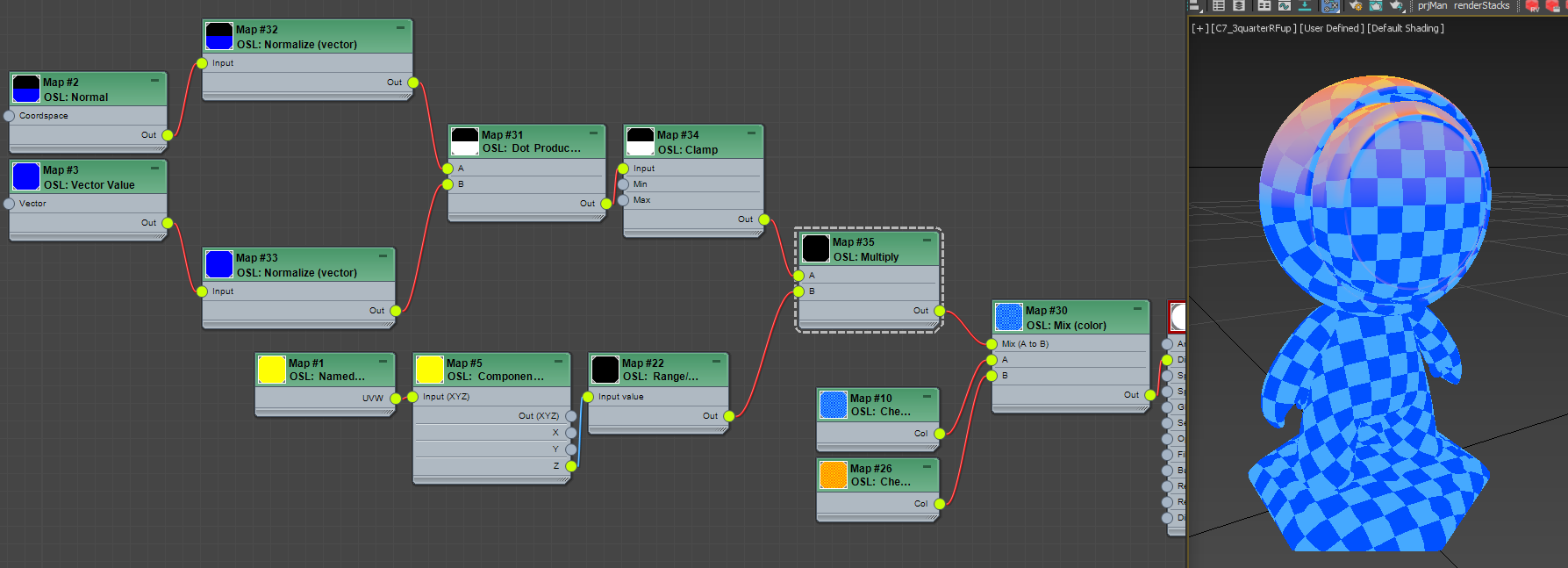
OK. Now we have 2 map trees. One for blending by height. Another one for the direction. We want to combine both so we can have blue check only at the top of Mat’s head. For this kinds of case, we can simply multiply two masks.
Select Range/Remapper. Set Input Range Start to 3.0, Input Range End to 4.0. This should move mas above Mat’s head.
Make a Maps > OSL > Math Float > Multiply map
Connect Out of Range/Remapper to A of Multiply.
Connect Out of Clamp to B of Multiply.
I know… after all those node, what you got is not that cool. But, this is how you learn.
In this tutorial…
we learned how to get position and normal information from the scene
how to utilize normal with dot product
many of frequently used important math maps such as Range/Remapper, Clamp, Normalize, Multiply. Component.
BUT! Yes, there is always BUT!
The portion that we used to make a mask by face normal exist as one map, Falloff map. This map is basically same as the map tree we set up with a bunch of maps. It take cares Normalize and Clamp, it also have option to map ti the different range. It also allow to define each end as color which is same as Remapping the result with Gradient.
In Falloff map, you have coordinate to choose just like Normal map. You have Face and Away color for each end. Facemeans the color when dot product is 1.o. Awayis the color when dot product is 0 because Type is Perpendicular/Parallel. If you switch to Toward/Away. The Color will map between dot product 1.0 to -1.0.
Welcome to my second OSL tutorial. Again, we will not write a single line of code in this tutorial. We will use SlateME as our OSL editor. Let me say it again, YOU DON’T NEED TO KNOW HOW TO CODE TO USE OSL IN 3dsMax.
I don’t want to spoil the ending. But, you should read til the end. 🙂
One of the advantage(or could be disadvantage for some users) of using OSL in 3dsMax is that it brings more granular and lower level of control which provide a greater flexibility. But, it also means that user need to learn and understand a new way of thinking(or workflow). Again it doesn’t mean you need to learn to code. But, you need to understand how and what kinds of data is flowing between lower level maps and how to control them. So, please try pay more attention to the explanation of “why” I’m connect port A to port B instead of memorizing map tree. 🙂
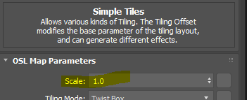
Today’s goal is randomizing textures in the tiles of Simple Tiles OSL shader so we can get infinite random tile texture from a few texture files.
Open SlateME.
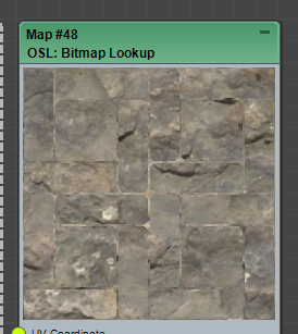
Make a Simple Tiles map. Maps > OSL > Textures > Simple Tiles. This is an equivalent of Tiles legacy map. You can make a various tile or brick patterns.
Double click the thumbnail so we can have a bugger thumbnail.
Change Tiling Mode to Twist Box.
As you can see, OSL can output not only color information but also various data information. For this tutorial, we will mainly utilize Indexdata which is a integer index number for individual tiles. Let’s see that it means visually.
Make 2 OSL > Math Float > Random by Index.
Connect Indexport of Simple Tiles to Idxof both Random by Index map.
So, what’s happening here?
Random by Index map generates a random float number between Min and Max and drives the randomization with the Idxand Seedparameters.
Since Idx of Random by Index is provided by the Indexvalue of Simple Tiles, all pixels in the same tile will get the same random value.You can see that well from the thumbnail, each tile has a different shade of gray.
But, you can see both map has exactly same pattern and color. That’s because both map has same Seednumber by default. What is the Seed number? This is from the Wikipedia. “A random seed (or seed state, or just seed) is a number (or vector) used to initialize a pseudorandom number generator.”, which brings another important concept, pseudorandom.
In CG, we can not use true random number, if a number is truly random. That means every time when you render or even open file again. You will have a different number and different pattern! Therefore, all random number in CG is pseudorandom driven by Seed number. If Seed number is same you get the same ransom number just like the above image.
Select the bottom Random by Index map
Set Seed to “77”, You should get this.
OK. let’s make a bunch more maps and actually do something with these 2 random maps.
Make the following maps OSL > Math Vector > Component (Vector) OSL > UVWCoordinates > UVW Transform OSL > BitmapLookUp
Choose “C:\Program Files\Autodesk\3ds Max 2021\maps\uvwunwrap\uv_checker.png” for BitmapLookUp This is a new 4k UV template which is added in 2021.
Connect Outof the top Random by Index > Xof Component (Vector)
Connect Outof the bottom Random by Index > Y of Component (Vector)
Connect Outof the Component (Vector) > Offset of UVW Transform Do not connect anything to BitmapLookUp yet.
The 2 Random by Index we made were for the random Offsetvalue of UVW, and it is a vector value. How do I know? If you see in UI, you can ses that it is made out of 3 values. The, it is a vector value.
So, we can not directly plug 2 float values into the Offset port. We need to assemble a vector data and plug into Offset. Component (Vector) map allow to compose or decompose a vector from/to 3 floats. Since we need to use only X and Y value. you don’t have to plug anything into Z. If no map is connected to the property, OSL map will use the value in the UI which was 0.
What we got so far? As you see in the thumbnail of UVW Transform, we randomly offset UV per tile. If you see more red, that means the pixel is offset more along U. If you see more green, that means the pixel is offset more along V. Remember Slate can only show any value range from 0-1 because it is made for color. Fortunately this case out data range is also 0-1. So, we could see what’s going on as image. But, it would be be the case all the time.
Now Connect UVWof the UVW Transform > UV Coordinates of BitmapLookUp Tada! you can see your texture randomly offset by Tile ID.
Cool. Now how can I control the scale of texture? Yes, you change the Scalevalue of UVW Transform.
How can I control the size of tiles? Scalein Simple Tiles.
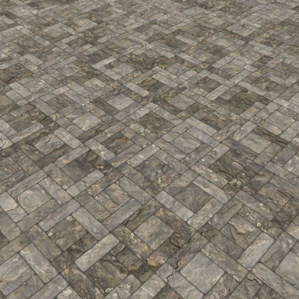
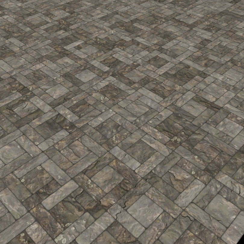
Let’s see what it looks like with a real texture. Remember this technique only works with seamless tileable texture. This is with the TexturesCom_RockSmooth0172_1_seamless_S.jpg from here. https://www.textures.com/. I use scale to 5.0 for UV.
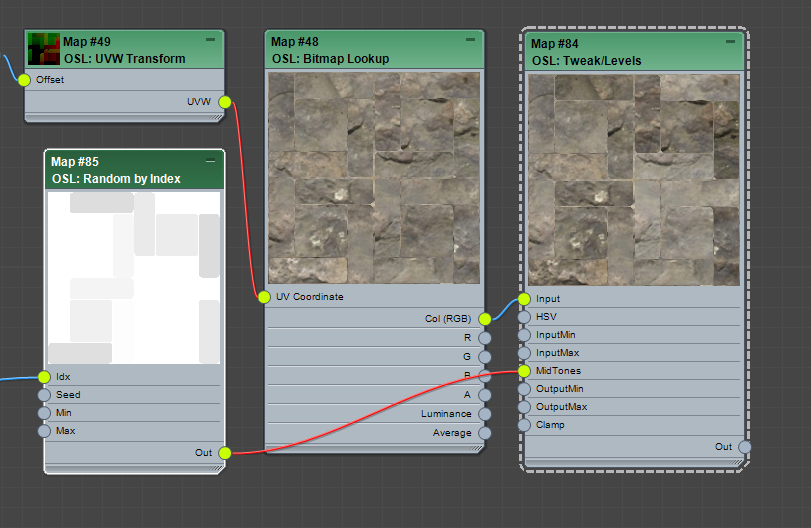
How about some mid tone variation? We can use Tweak/Levels OSL map for this. We will also need another Random by Index map driven by Index.
Select one of Random by Index map and SHIFT+drag to make a copy.
Set Minas 0.75, Maxas 1.25. Seedas 131.
Add a OSL > Tweak/Levels map.
Connect Out of the new Random by Index map to MidTones of Tweak/Levels.
Connect Out(RGB) of BitmapLookUp map to the Input of Tweak/Levels.
OK, I hope you get the hang of how to wrangle data to drive values at this point. Next, let’s put the gaps in. There are unlimited ways to how to handle gaps. But, I’ll just go easiest way since the main purpose of this post is tutorial. The Bumpoutput of Simple Tiles map already give you a black gaps and white tiles. I’ll use that output to composite with Multiplymode.
Make OSL > Compositing > Composite map.
Connect Outof the Tweak/Levels > Bottom layer RGB of Composite
Connect Bumpof the Simple Tiles > Top layer RGB of Composite
Set Top layer Alpha as 0.7, BlendMode as Multiply.
OK, it is getting there. Let’s add one more randomization, the rotation. By now, you should already know what to do.Yes, you need to have another Random by Index (Float) with range 0.1 – 360 and feed into Rotateof UVW Transform. BUT, since it is a tutorial, let’s make things more complicate to learn. What if we want to rotate only at right angle like 90, 180, 270 degree?
Our goal is get only one of the 0, 90, 180. 270 per tile. How we do that? Right, we can get a random value between 0 – 3 and multiply 90.0. But, Random by Index (Float) generates float number, and we don’t have Random by Index (Integer) map. Well, don’t worry. Here comes Float-to-Int map to the rescue!
Copy one of Random by Index (Float).
Set Minas 0.0, Maxas 3.99. Seedas 666.
Make OSL > Math Float > Float-to-Int map
Set Modeas floor.
Make OSL > Math Float > Multiply map
Set Bas 90.0
Connect Outof the new Random by Index map to Inputof Float-to-Int.
Connect Out of the Float-to-Int map to A of Multiply
Connect Outof the Multiply map to Rotateof UVW Transform. You may wonder why 3.99 instead of 3.00, and what the heck is “floor”? Floor is a way to convert a float value to integer value by returning the largest whole number (integer) that is less than or equal to the number. if you had 1.24, you would get 1.o. So, it is a floor of the range 1.0-2.0. There is also “ceil” which is kinda opposite. The ceil of 1.24 would be 2.0. By setting range as 0.0-3.99 and mode as floor, we are trying to make sure all 4 numbers are getting even chance. 0.0-1;0 > 0.0. 1.0-1.99 > 1, 2.0-2.99 > 2.0. 3.0-3.99 > 3.0. Left is without the rotation randomization. Right is with the rotation randomization.
As you can see, you can randomize any parameters you want. You just need to know when to stop. Should we stop now then? No, not yet. So far, we have used only one map file and looks like getting a good result. But, what if we can use multiple map files and randomly use per file?
Here is a great news. One of the new feature of 3dsMax 2021.2 is 1-of-N(Filename) map. If we don’t have this map, we have to setup a small tree with multiple BitmapLookup , 1-of-N Switcher and Random by Index map. Now we just need 2 maps.
Add a OSL > Switchers > 1-of-N(Filename) map.
Choose all 5 maps.
Add a OSL > Switchers > Random Index by Number/Color map. BTW, such a great map, I wonder who made this? 🙂
Connect Indexof the Simple Tiles map toInput Numberof Random Index by Number/Color.
Connect Outof the Random Index by Number/Color to Filename of BitmapLookUp.
OK… This is the full tree. I guess we end up with not-so-mini-tutorial.
BUT! Yes, there is always. “BUT”.
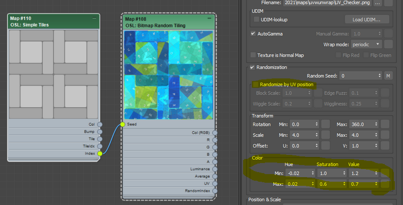
We went through all these to learn how to work with OSL maps to build own randomization. Now I have to tell you this. Sorry, we didn’t need to go through all these if you wanted to just use it. Why? Because Zap made the awesome Bitmap Random Tiling for 3dsMax 2021.2.
This is what it looks like if you use Bitmap Random Tiling. Youjust need to plug Indexinto Seed. Make sure to turn off Randomize by UV position.
You can even randomize color, too.
If you want to use multiple map file? Then, re-use the 1-of-N(Filename). Another 2021.2 feature.
I guess it is worth to upgrade??? 🙂
If you are really lazy, here is the max file. It has the full setup and simple 2021.2 setup. I can not include texture file. So, you probably need to download some seamless tileable maps. Here is another good news. Because ,max file actually embed the source OSL code in the scene file, you can even open this file in 2019. You will see the new 2021.2 OSL shader there. Save the OSL map in a material library. Then, you can even use the new map in 2019 or 2020. Another nice thing about 3dsMax OSL implementation!
A teaser for the future article! What is the difference between the following 4 images?
The answer is… they all rendered in a different renderer. From the left, Corona, VRay, VRayGPU, Arnold. Yes, all different renderer. You can have exactly same map tree across different renderer even CPU/GPU. I can say this is the first time I ever see this is possible in CG history. I’ll have a blog post with more examples in the future.
Let me just borrow text from 3dsMax help. You guys should read manual all the time’ Three are many good in formation! I highlighted important aspect of 3dsMax OSL map for you!
Open shading language (OSL) is an open source shading language that is fairly simple to understand. It can be used in several different ways. You can use the OSL Map, which is an execution environment for OSL shaders inside of 3ds Max, and it works like any regular built-in 3ds Max map. There is also a category of pre-loaded OSL maps that you can easily use. In addition, you can use any OSL maps you download from the internet. Finally, you can creating a shader or map in OSL using our development tools. This is a much simpler method to create custom maps than developing the equivalent functionality as a 3ds Max C++ map.
OSL works in any renderersupporting the regular 3ds Max shading API (Scanline, vRay, Corona, etc.). It also works outside of renderers, anywhere in 3ds Max where a regular map is requested, such as in the Displacement modifier. It also works with renderers that support OSL natively, such as Arnold. In those cases, the execution environment inside the OSL map is not sued, instead, the OSL source code, the parameter values and shader bindings are sent to the renderer, which executes the OSL code. More renderers supporting OSL natively are appearing daily.
OSL uses “just-in-time” compilation and optimization of entire shade trees at once, as long as all the shaders in the shade tree are OSL shaders. You can mix OSL shaders and regular shaders, but the optimizations will suffer.
First of all, I really really want to make sure about this.
3dsMax OSL is seamlessly integrated just like all other C++ maps. There is ZERO difference in terms of how to use and where you can use. Also if you chain OSL map together, 3dsMax combine them the entire OSL chain and make a single shader under the hood. Essentially Slate ME is acting as an OSL node editor for you. Even better 3dsMax 2021 ships with 123 build-in shaders to start with. At these point, almost all 3dsMax legacy map could be replace with OSL. This mini tutorial is a very good example of using Slate ME as an OSL node editor.
In this tutorial, the blender guru is using a custom tool in order to randomize the uv’s rotation so we can’t see anymore the repetitive pattern on a large scale tiling texture. He says that, as far as he knows, this kind of tool doesn’t exist in any other 3d software because it involves maths tricks and vectors and nobody wants to deal with this.
Good news! you don’t need custom node for this. Master Zap let me know how to do this with built-in OSL node. I’m posting the master;s answer with my explanation so you can go further.
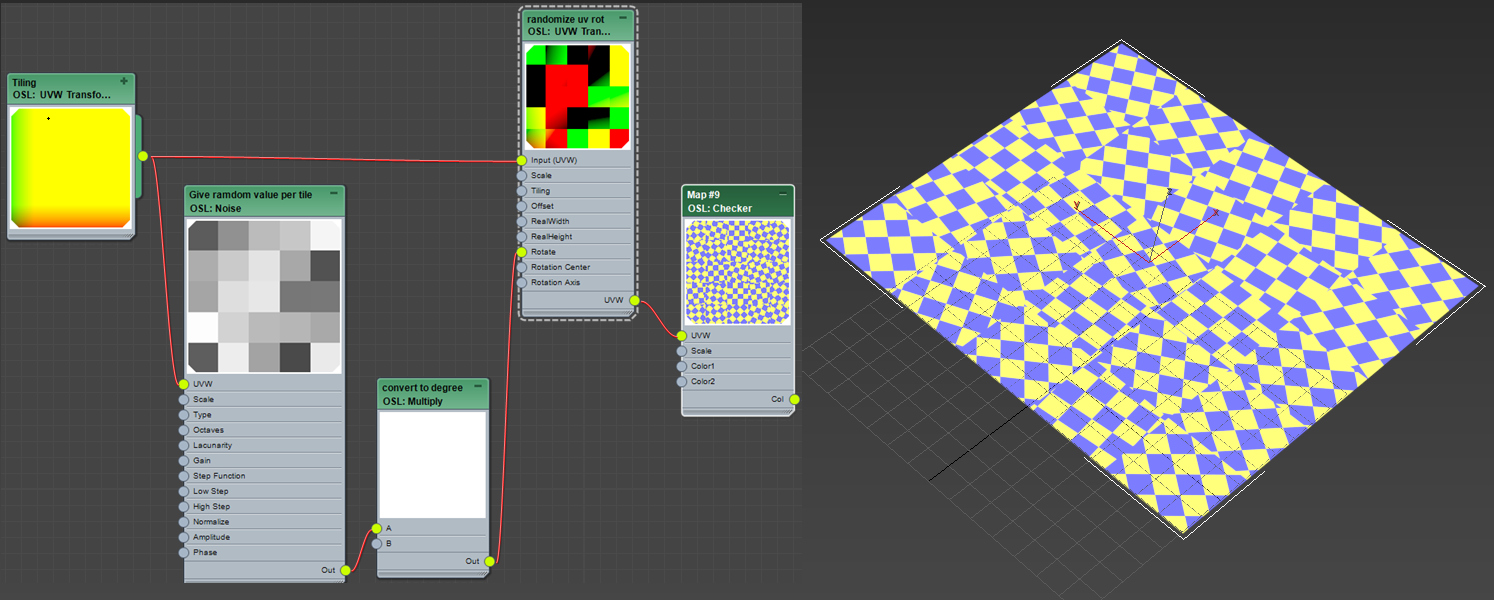
First, this is the graph. 4 nodes!
Let’s see one by one.
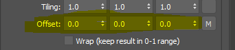
UVTransform : Tiling
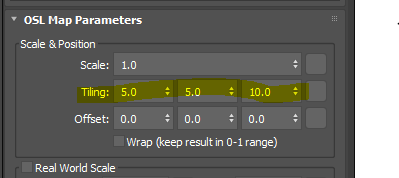
This OSL map is like Coordinate rollout in other maps. It allows you to move, rotate and scale uv coordinate. I tiled uv coordinate here. So, I tilted here with Tiling parameters.
Tip! You can connect one UVTransform to many OSL maps whicn means you can control the coordinate of all those map at once.
Noise : Give random value per tile
This map generates a random 0-1 value per tile which will be used as rotation value later.
As the name says, it is an OSL version of Noise map. It has 6 types of noise in a map. We will use Cell type which makes random pixel bitmap patter.
Then, set Scale to 1.0 and Octave to 1. This makes the noise function generates one value per tile. If you increase Scale or Octave, it will essentially divide each tile.
Then, turn off Step Function to prevent blending.
Multiply : convert to degree
Multiply 360 so we can get rotation value between 0-360. As you can see, you don’t have to make a map for value B. You can just type in B parameters of the map.
UVTransform : randomize uv rot
This map rotates UV per tile. You don;t need to set any value here. Just connect UVTransform : Tiling to Input(UVW) which inherit tiling from UVTransform : Tiling map. Then, connect Multiply : convert to degree to Rotate.
Now you can connect this map to any maps UVW port.
I have been using jpg sequence for my Make Preview output. It is allways easier and more flexible to deal with image sequence than avi, mov or mp4.
The problem is Make Preview windows is the one of the old window which doesn’t have full exposure to Mmaxscript. 3dsMax dev added more argument for createPreview method in 3dsMax 2020. But, unfortunately some of option in the Make Preview dialog is still not available for Maxscript.
But, that doesn’t mean you can not set Make Preview automatically. 3dsMax has the ultimate hack(?) for controlling any UI component. UIAccessor and DialogMonitorOPS.
This allow you to emulate user interaction with UI like clicking button, choosing dropdown items and pressing Enter with Maxscript.
If you don’t want all these, Download the final template.
Skeleton code of DialogMonitorOPS
Let’s start with very simple script.
fn setMakePreview = (
local WindowHandle = DialogMonitorOPS.GetWindowHandle()
local WindowTitle =  (UIAccessor.GetWindowText WindowHandle)

if WindowTitle == "Make Preview" then (
print "Hello"
)
True
)

DialogMonitorOPS.enabled = true
DialogMonitorOPS.RegisterNotification setMakePreview id:#setMakePreview

max preview

DialogMonitorOPS.unRegisterNotification id:#setMakePreview
DialogMonitorOPS.enabled = false
DialogMonitorOPS.enabled = true
First, you need to turn on DialogMonitorOPS.so 3dsMax can monitor any UI. Of course, you don’t want to turn on this all the time. So, after our job is done, we will turn off.
Unresister setMakePreview and turn off DialogMonitorOPS
Now let’s see the setMakePreview fucntion. This function will run all the time while DialogMonitorOPS is running.
The most important thing to know is that this function need to return true at the end. I forgot why. But, you MUST do it. So, just do it.
local WindowHandle = DialogMonitorOPS.GetWindowHandle()
How would you let Maxscript know which UI you want to control? We will use window handle or hwnd which is a unique id of each UI element. The above line will give is the handle of window which DialogMonitorOPS detected.
local WindowTitle = (UIAccessor.GetWindowText WindowHandle)
Then, this above line will give us the title of dialog.
if WindowTitle == “Make Preview” then ( print “Hello” ) True
DialogMonitorOPS will check if the dialog is “Make Preview” dialog. If so, it will print Hello.
Let’s set custom output path
From now on I’ll only show setMakePreview function.
fn setMakePreview = (
local WindowHandle = DialogMonitorOPS.GetWindowHandle()
local WIndowTitle =  (UIAccessor.GetWindowText WindowHandle)

if WindowTitle == "Make Preview" then (
for i in (windows.getChildrenHWND WindowHandle) do (format "%\n" i)
UIAccessor.PressButtonByName WindowHandle "File..."
)
True
)
I removed print “Hello” and added UIAccessor.PressButtonByName WindowHandle “File…”. As you can read, this will find a button named “File…” and press it for you.
for i in (windows.getChildrenHWND WindowHandle) do (format “%\n” i)
What does this do? It just printed a bunch of things in Maxscript listener. This is how we sees what kinds of UI element is in the current dialog and fid a way to access each UI element. As I said in the begining, we use windows handle to specify UI element. This line will print out the information of all children of the dialog with given handle, Make Preview dialog. it gives us an array for each UI element. The important ones are first(hwnd of child), forth(UI type) and fifth( displayed text).
fn setMakePreview = (
local WindowHandle = DialogMonitorOPS.GetWindowHandle()
local WindowTitle =  (UIAccessor.GetWindowText WindowHandle)

if WindowTitle == "Make Preview" then (
UIAccessor.PressButtonByName WindowHandle "File..."
)
if WindowTitle == "Create Animated Sequence File..." then (
-- Set cusom output path
local edits = for i in (windows.getChildrenHWND WindowHandle) where i[4] == "Edit" collect i[1]
uiaccessor.setwindowtext edits[1] @"c:\temp\test_.jpg"
UIAccessor.PressButtonByName WindowHandle "&Save"
)
True
)
Because we pressed “File…” button. A new dialog pops up, “Create Animated Sequence File…”. In this dialog, we need to these.
Set custom output path
Set Save as Type to jpg
Press Save button
To set custom output path, we need to know hwnd of path input UI. But, if you check fifth item of array. Text input doesn’t have name! What should I do? Other information we have is type of control on fourth item. The type UI you can input text is “Edit”. So, I collected hwnd of “Edit”s. Fortunately 3dsMax seems collecting UI info in the same order from top to bottom. So, let’s try on the first one. You can use uiaccessor.setwindowtext to set value on Spinner of Edit. If you want to use own naming convention. Replace @”c:\temp\test_.jpg” with own function or variable.
Wait? why the name iis “&Save”. How do I know I need &? I also don’t know where & come from. But, I know “Save” did not work. So, I printed out all child UI elem data and checked the names.
Did it work? Maybe or Maybe not. Because 3dsmax remembers the format you used last time, if it was not jpg, Make Preview window will automatically switch to the format. So, we need to choose jpg from format dropdown. Now this is real fun!
fn setMakePreview = (
local WindowHandle = DialogMonitorOPS.GetWindowHandle()
local WindowTitle =  (UIAccessor.GetWindowText WindowHandle)

if WindowTitle == "Make Preview" then (
UIAccessor.PressButtonByName WindowHandle "File..."
)
if WindowTitle == "Create Animated Sequence File..." then (

local edits = for i in (windows.getChildrenHWND WindowHandle) where i[4] == "Edit" collect i[1]
uiaccessor.setwindowtext edits[1] @"c:\temp\reallyanothertest_.jpg"

local comboboxes = for i in (windows.getChildrenHWND WindowHandle) where i[4] == "ComboBox" collect i[1]
local filetypeHwnd = comboboxes[3]

local CB_SHOWDROPDOWN = 0x014F
local CB_SETCURSEL = 0x014E
local WM_LBUTTONDOWN = 0x0201
local WM_LBUTTONUP = 0x0202
windows.sendMessage filetypeHwnd CB_SHOWDROPDOWN 1 0 -- Open combobox dropdown
windows.sendMessage filetypeHwnd CB_SETCURSEL 7 0 -- Select 7th item
windows.sendMessage filetypeHwnd WM_LBUTTONDOWN 0 -1  -- Press left mouse button
windows.sendMessage filetypeHwnd WM_LBUTTONUP 0 -1  -- Raise left mouse button
windows.sendMessage filetypeHwnd CB_SHOWDROPDOWN 0 0    -- Close dropdown

UIAccessor.PressButtonByName WindowHandle "&Save"
)
True
)
I guess you already have figured out what this does. Yes, it collect hwnd of all comboboxes.Them 3rd one was the Save As Type dropdown.
local comboboxes = for i in (windows.getChildrenHWND WindowHandle) where i[4] == “ComboBox” collect i[1] local filetypeHwnd = comboboxes[3]
All cool. Butn thet the heck is the next lines?
windows.sendMessage Sends a Win32 message to the HWND specified in the first argument. This is how you emulate UI interaction programmatically.
I commented on the code what each lines does. But, you may think how am I suppose to know all the secret code?
CGTalk maxscript forum has a lot of answers for common operations. You can also google windows message reference like this.
Now since you set jpg as a new format, JPEG Image Control windows pops up. This one is easy. We can just press OK button like this.
if WIndowTitle == “JPEG Image Control” then ( UIAccessor.PressButtonByName WindowHandle “OK” )
How about other controls like checkbox?
Since checkbox text usually doesn’t change, we can search the string pattern of fifth item to find hwnd. This is function to get hwnd using UI name. Then you can BM_SETCHECK window message to check the checkbox. if the first argument is 1, the chebox will be checked. If it is 0, the checkbox will be unchecked.
fn getChildHwndByName parent_hwnd childUIname = (
    local child_hwnd = 0
    for i in (windows.getChildrenHWND parent_hwnd) where matchPattern i[5] pattern:childUIname do (child_hwnd = i[1])
    child_hwnd
)
local frameNumHwnd = (getChildHwndByName WindowHandle  "Frame Numbers" )
windows.sendMessage frameNumHwnd BM_SETCHECK 1 0
Runscript after Make Preview is done
If you want to automatically run image sequence player like PDPlayer or RAMPlayer or resister to Shotgun, simple add the code after max preview.
Final template code
Here is the cleaned final template code. If you don’t want to read all this, start from this.
This is made in 3dsMax 2019. Other version might not work with this if there is UI difference.
3dsMax 2020 Preview Enhancement
3dsMax 2020 has some nice improvement for Make Preview.
Much faster. 1.5 – 3x faster creation on local drives
Capture size greater than viewport dimensions supported
“Quality” setting accessible from Preview UI (Nitrous only)
Default preview filename based on current scene filename
100% output resolution on by default
MXS snippet can be executed per frame for custom strings
Filename and MXS snippet values can be specified from MXS command line of CreatePreview()
After executing the preview, the time slider is returned to the original starting frame
“Play when done” accessible from Preview UI
If running from MXS command line, avoid dialog boxes, output to listener instead
3dsMax 2020 also has the bug fix for “User defined” Per-view preset missing issue. This issue is related to the permission. If you are still on older version. Make sure to open the permission for folders under 3dsMax root to be able to choose “User Defined” Per-view preset in Make Preview. Or, upgrade to 2020.


 How Push modifier works is really really simple. It moves each verts along the its normal by the given amount. As you can see, Push modifier only has one parameter which is the distance the verts are moved along normals.
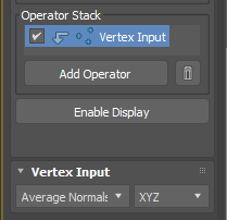
 3dsMax OSL has


 How about X = 1.0 and Y, X =0.0?

 Open SlateME.
 Make 2 OSL > Math Float > Random by Index.


 As you can see, you can randomize any parameters you want. You just need to know when to stop. Should we stop now then? No, not yet. So far, we have used only one map file and looks like getting a good result. But, what if we can use multiple map files and randomly use per file?