We, 3dsMax users, love 3rd party scripts and plugins. But, we don’t necessarily like the process of installing and managing those. Sometimes this is one of the reasons why we don’t even upgrade 3dsMax. In this post, I’ll show you how to decouple the installation of 3rd party scripts from 3dsMax for easier management. I will also show how the new pipeline integration feature in 3dsMax 2022.3 will make this task simpler. We will use the famous Soulburn script as an example.
First, we need to know how scripts are loaded when 3dsMax launches. Fortunately there is already very good documentation here. In a nutshell, 3dsMax executes startup scripts and macros scripts from certain locations while being launched. Users need to install scripts in those locations so they can be loaded properly.
Startup scripts
There are a few reasons why users would want to execute scripts automatically when 3dsMax starts. For example, If you use any scripted plugins such as the famous Paul’s PEN_Attribute_Holder, you probably want it to be loaded and ready to use just like C++ plugins. Another important use of startup script is setting working environments, defaults and system directories which we will utilize in this post. I also have a separate post about this subject here. Please check it out.
As you see in the above document, 3dsMax reads the startup script from the various places. But, the most commonly used folders are these two folders.
- system startup scripts folder – C:\Program Files\Autodesk\3ds Max 2022\scripts\Startup
- user startup scripts folder – C:\Users\[username]\AppData\Local\Autodesk\3dsMax\2022 – 64bit\ENU\scripts\startup
One of the important rules of 3dsMax tool management is you never touch the 3dsMax root folder. If you need to add/modify anything, you should add/modify files in the appdata folder which is usually called the “ENU” folder. C:\Users\[username]\AppData\Local\Autodesk\3dsMax\2022 – 64bit\ENU\
But, as you can see, using a user data folder brings a lot of challenges, especially for a team. So, I have been managing startup scripts using a seed startup script, [3dsMax root]/scripts/startup.ms. This script basically calls the real script like this.
FileIn @ "D:\PROJECT\_maxDefault\startup\mystartup.ms"
By using this seed script, I can update the startup script centrally without re-depolying again to all workstations. this is one of two files I allow an exception personally.
BUT! I don’t need this seed script anymore because of the new pipeline integration feature. This feature allows users to set various paths used by 3dsMax with Environment variables which means you can set paths from the outside of 3dsMax before it launches. Even though 3dsMax provides a great amount of control over every aspect of 3dsMax with Maxscript. The fundamental limitation of the script based approach is that everything happens after 3dsMax launched. The new pipeline integration removes this limitation. Also it allows you to control folders that never have been allowed to control before such as the appdata folder itself.
So, how can we use this feature? There are 2 ways to set environment variables in Windows.
- The first one is setting in System Properties or using a group policy. As you can already see, IT dept. would love this central management.
- The second way is using a batch file or Python to set env var only for the session. If your studio is using a launcher, they are already using this way.
For startup script, we can use the first method since scripts are usually compatible between 3dsMax versions and you can put a condition if there are any version specific things in it.

After I added “ADSK_3DSMAX_STARTUPSCRIPTS_ADDON_DIR” env var, my 3dsMax runs any scripts in this folder. I don’t need to add anything to 3dsMax root folder. I don’t need to worry about re-coying again this file after wiping out ENU folder to solve my 3dsMax issues. I don’t even need to do anything for any future version of 3dsMax. It is truly set it and forget it!
Setting custom system directories with startup script
Even though the new pipeline integration allows you to add “scripts” folders with “ADSK_3DSMAX_SCRIPTS_ADDON_DIR”. This folder actually doesn’t matter much because we never execute all scripts in these folders automatically. Also setting env var doesn’t actually change 3dsMax system directories, and most scripts are usually called other scripts or macroscript(We will discuss it later) using #scripts or #userScripts system directories to allow more flexible installation instead of hard-coded path. For example, this is a macroscript from the Soulburn script.
MacroScript blendedBoxMapMaker category:"SoulburnScripts" tooltip:"blendedBoxMapMaker" Icon:#("SoulburnScripts_blendedBoxMapMaker",1)
(
Include "$scripts/SoulburnScripts/scripts/blendedBoxMapMaker.ms"
on execute do blendedBoxMapMakerDefaults()
on Altexecute type do blendedBoxMapMakerUI()
)
As you can see, this action will try to find “/SoulburnScripts/scripts/blendedBoxMapMaker.ms” file under #scripts folder($scripts is a symbolic pathname for #scripts).
By default #scripts is set to C:\Program Files\Autodesk\3ds Max 2022\scripts and #userScripts is set to C:\Users\ChangsooEun\AppData\Local\Autodesk\3dsMax\2022 – 64bit\ENU\scripts. 3rd party scripts are suppose to use #userScripts. This means that we have to install the Soulburn script files under C:\Program Files\Autodesk\3ds Max 2022\scripts unless we change the location.
The good news is that we can change any system directories using the “setdir” Maxscript command! This is the first two lines of my startup script. This allows me to install any 3rd party script under D:\PROJECT\_maxDefault\scripts\ instead of 3dsMax root or my user folder.
setdir #scripts @"D:\PROJECT\_maxDefault\scripts\"
setdir #userscripts @"D:\PROJECT\_maxDefault\scripts\"
TIP! As you can see from the 3dsMax system directories document, you can also set any project folders using “setdir” command. By default, they are set as a relative path to the current project folder. But, you can change those using “setdir“ command. For example, you can change autoback folder to “D:\3dsMax_Autoback” instead of in your Document folder.
setdir #autoback @"D:\3dsMax_Autoback"
Macroscripts
Macroscript is a script that defines “ActionItems” in 3dsMax. ActionItem is “that represents the action that can be assigned to Toolbars, Menus, QuadMenus and Keyboard Shortcuts using the Customize User Interface dialog”. Basically if you want to make an UI like a button or shortcut, you need a macroscript for the script. It also allows the script to show up in Global Search(X menu).
3dsMax executes the macroscripts in #userMacros and #macroScripts system directories by default when it starts. Now you may think we could change these folder to own custom folder like #scripts and #userscripts. BUT! We can’t do that for macroscript because 3dsMax and many 3rd parties actually use these folders. BTW, there is the new Autodesk Application Plug-in Package format which 3rd parties can completely separate their files from 3dsMax factory installation. If your favorite plugin doesn’t support this. Ask them!
Another problem of #userMacros folder is that it is used when user create macroscript by drag and drop. For example, if I type print “Hello, World” and drag and drop this line to a toolbar. 3dsMax makes “DragAndDrop-Macro1.mcr” under #userscripts folder. If you share this folder across many users, you will get macroscript from all your teammates.
Therefore, it is better to load the commonly shared macroscripts from an added folder using “ADSK_3DSMAX_MACROS_ADDON_DIR” env var.

If you are using 3dsMax without the pipeline integration, you have a few ways to do this.
- Copy all .mcr files to #userMacros folder.
- Just run all .mcr files with the “FileIn” function.
- You can copy to the 3dsMax root folder. But, I wouldn’t recommend it.
Honestly none of the above options are good. This just shows how beneficial the new pipeline integration is.
Icons
This is the last piece of puzzle for 3rd party script management. Sometimes 3rd party scripts include icon files. We can use both startup script or env var for this. It doesn’t matter much. I choose to use “ADSK_3DSMAX_ICONS_ADDON_DIR” env var.

If you are using older version of 3dsMax, I will just set #usericons folder in a startup script.
Let’s put together all the pieces for Soulburn script
I have set 3 environment variables.
- ADSK_3DSMAX_STARTUPSCRIPTS_ADDON_DIR = D:\PROJECT\_maxDefault\startup
- ADSK_3DSMAX_MACROS_ADDON_DIR = D:\PROJECT\_maxDefault\usermacros
- ADSK_3DSMAX_ICONS_ADDON_DIR = D:\PROJECT\_maxDefault\usericons
I have set 2 system directories in a startup script in D:\PROJECT\_maxDefault\startup
folder(ADSK_3DSMAX_STARTUPSCRIPTS_ADDON_DIR).
- setdir #scripts @”D:\PROJECT\_maxDefault\scripts\”
- setdir #userscripts @”D:\PROJECT\_maxDefault\scripts\”
If you download the SoulburnScriptsPack_3dsMax_v112_R2013toR2022.zip file, it has 3 folders.

- Copy all files in “MacroScripts” folder to D:\PROJECT\_maxDefault\usermacros (ADSK_3DSMAX_MACROS_ADDON_DIR)
- Copy “SoulburnScripts” folder in “scripts” folder to D:\PROJECT\_maxDefault\scripts\ (#scripts)
- Copy all files in “\UI_ln\IconsDark” or “\UI_ln\Icons” folder to D:\PROJECT\_maxDefault\usericons (ADSK_3DSMAX_ICONS_ADDON_DIR).
You can’t use “Icons” or “IconsDark” folder in #usericons folder. .bmp icons are only supported for backward compatibility since 3dsMax 2017. If you want to have a different set of icons per theme, you need to use the new .png icon naming convention and “iconname:” argument. The details are here.
Now I have the Soulburn script in my 3dsMax 2021, 2022 and will have them in the whatever future version of 3dsMax without any more steps. I can nuke the ENU folder anytime without worrying about re-installing these scripts.
This also works with any 3rd party scripts.
- If they are .mcr files, put in the ADSK_3DSMAX_MACROS_ADDON_DIR folder.
- If they are .ms files, put in the #scripts folder.
- If they have icons, put in the ADSK_3DSMAX_ICONS_ADDON_DIR folder.
To help your understanding, I’ll give one more example, another famous script, DebrisMaker2.
In this case, the downloaded file is .mzp file. This is a self-installation zip file. You can actually unzip with any zip uncompressor such as 7-zip.
If you unzip, it has 3 folders under “DebrisMaker2.0” folder. Guess where would you need to copy the files?
- MacroScripts -> D:\PROJECT\_maxDefault\usermacros
- Scripts -> D:\PROJECT\_maxDefault\scripts\
- UI_ln\Icons -> D:\PROJECT\_maxDefault\usericons
Again, now you will have DebrisMaker2 in any 3dsMax 2021 and above!
Before I finish this post. Someone might wonders why I said “3dsMax 2021 and above”. Isn’t it a new feature of 3dsMax 2022.3? Yes, right. It is officially added to 3dsMax 2022.3 with more complete support. But, 3dsMax 2021.3 actually have had some env var support for Autodesk internal use. At least, the 3 env var we have utilized work for 2021.3, too. I let you know because setting env var as system env var will affect 2021.3. I don’t want you to be confused or surprised.
If you want to use the pipeline integration for only certain version of 3dsMax, you have to use batch file of Python script which I will cover in the next post.


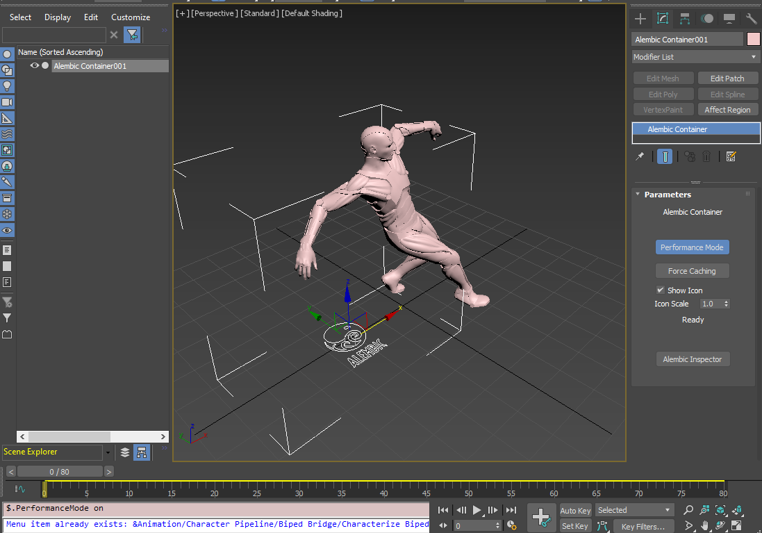
 Now if you go to any frames, that frame will be cached or play animation while turn off Real time playback to make sure for max to evaluate every frame.
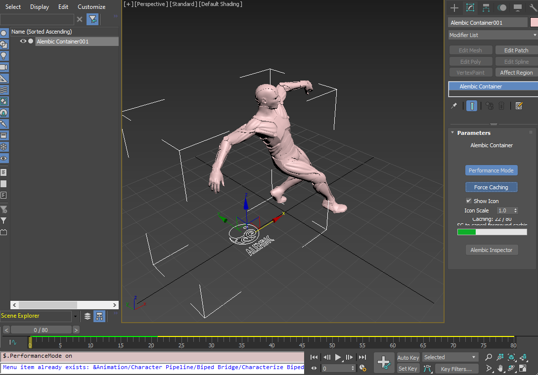

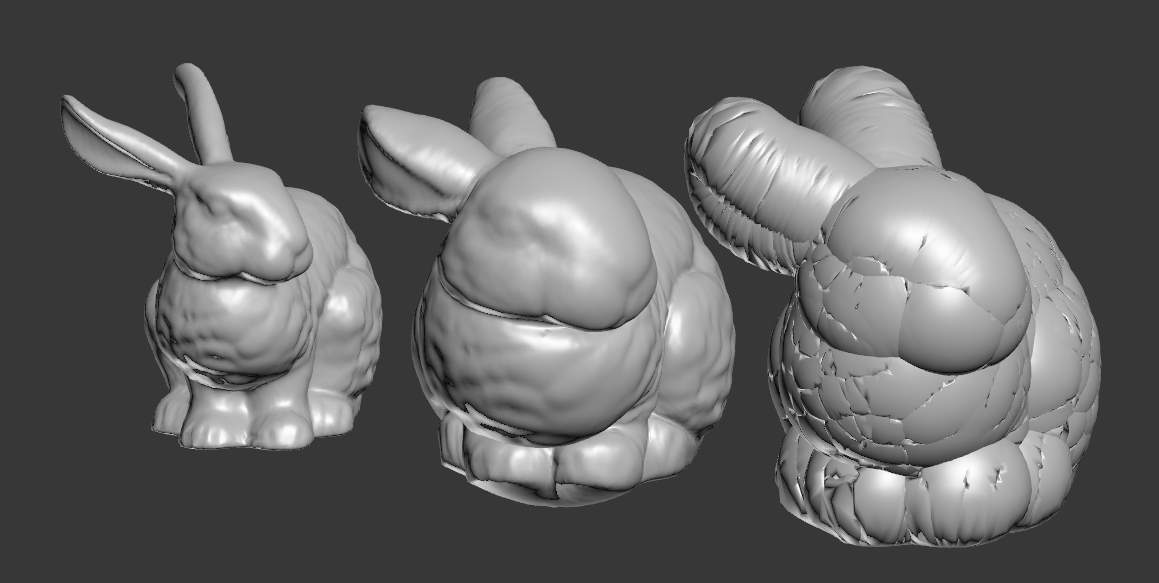
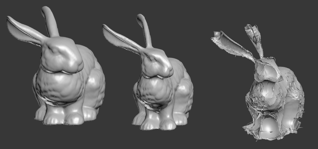
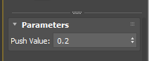 How Push modifier works is really really simple. It moves each verts along the its normal by the given amount. As you can see, Push modifier only has one parameter which is the distance the verts are moved along normals.